
User Manual


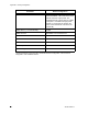


Table Of Contents

28 APCD-LM047-1.1
Appendix B: Ethernet Cables and Connectors
Table 7 Ethernet Interface Specifications
The following table and figures show the definitions of wiring for T568A and T568B
connectors, used to make cross-over and straight-through Ethernet cables as found in ANSI/
TIA/EIA-568-B.2 “Balanced Twisted Pair Cabling Components”.
Table 8 Wiring T568A and T568B ends for Ethernet Cables
Straight-through Ethernet cables have T568A wiring at both ends while Cross-over cables
have T568A at one end and T568B at the other end.
EUM Physical Interface RJ45 (Ethernet) socket
Wiring standard TIA - T568A
Pin - Pair/Wire - Color
Pin 1 - 3/a - Green/White
Pin 2 - 3/b - Solid Green
Pin 3 - 2/a - Orange/White
Pin 4 - 1/b - Solid Blue
Pin 5 - 1/a - Blue/White
Pin 6 - 2/b - Solid Orange
Pin 7 - 4/a - Brown/White
Pin 8 - 4/b - Solid Brown
TX Data + (Output from EUM)
TX Data - (Output from EUM)
RX Data + (Input to EUM)
Not Used.
Not Used.
RX Data - (Input to EUM)
Not Used.
Not Used.
# Description T568A T568B
1 Connectors RJ-45 RJ-45
2 Wiring standard T568A T568B
3 Pair/Wire - Color
3/a – Green/White
3/b – Solid Green
2/a - Orange/White
1/b – Solid Blue
1/a – Blue/White
2/b – Solid Orange
4/a – Brown/White
4/b – Solid Brown
Pin 1
Pin 2
Pin 3
Pin 4
Pin 5
Pin 6
Pin 7
Pin 8
(Pins in bold are different
from T568A)
Pin 3
Pin 6
Pin 1
Pin 4
Pin 5
Pin 2
Pin 7
Pin 8