
User's Manual Part 2


322 APCD-LM043-8.0 (DRAFT C)
Appendix K: Sample IP Plan
Switched Ethernet and Through-Only Modes
The following tables provide an example of an IP plan for a small LMS4000 system equipped
with a single 900 MHz CAP and up to 4 CCUs:
•
CAP IP Addressing Plan on page 322
•
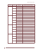
CCU Radio IP Addressing Plan on page 323
•
EUM IP Addressing Plan on page 323
•
Subscriber IP Addressing Plan on page 324
A maximum of 200 nodes (CCUs, EUMs, routers, and other backend equipment) will be
supported in a small network. The example given here is for a network with up to 200 hosts
and uses the following configuration:
• multiple radio subnets
• multi-homing on router
• private IP addresses for EUMs
• public IP addresses for subscribers (example uses the RFC recommended IP address
block for documentation)
• DHCP Relay at the CCU is disabled
• SNTP Relay is enabled at the CCU
• SNTP clients are enabled on the CCU and EUMs
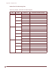
CAP IP Addressing Plan
Table 107 Example – CAP IP Addressing Plan
CAP Element IP Address
Gateway Router 192.168.10.1 /24
192.0.2.1 /24
172.16.4.1/22
172.16.8.1/22
172.16.12.1/22
172.16.16.1/22
CAP Switch 192.168.10.5 /24
CAP UPS 192.168.10.6 /24
SNMP Manager 192.168.10.7 /24