
User's Manual Part 1


60 APCD-LM043-8.0 (DRAFT C)
4: IP Network Planning
its Ethernet interface into promiscuous mode and see all Ethernet traffic to and from another
device on the same segment. For 10/100BaseT Ethernet, Ethernet devices connected directly,
through Ethernet hub(s) or through Ethernet repeater(s) are on the same segment. Ethernet
switches normally support one Ethernet segment per port since directed Ethernet traffic is
switched from a port to only one other port, once the switch has learned which Ethernet
devices are on which port. In all modes, the CCU radio interface is a switch, so EUMs are
always on separate Ethernet segments. Therefore, an EUM only receives directed Ethernet
packets destined for itself or any host on the Ethernet side of the EUM.
Ethernet Broadcast Domain—All of the Ethernet devices that receive an Ethernet broadcast
packet are considered to be on the same Ethernet broadcast domain. In general, this includes
all Ethernet segments connected by Ethernet switches. An Ethernet broadcast domain is
usually bounded by IP routers.
IP Broadcast Packet—An IP packet address to the subnetwork broadcast address. If the IP
subnet is 172.16.4.0 / 22, then 172.16.7.255 is the IP broadcast address for that subnetwork.
Older addressing schemes use 172.16.4.0 as well for the subnet broadcast address.
Radio Network—The radio network consists of the CCU radio interface, the EUMs, and the
subscribers. Note that if an IP router is attached to an EUM, other network(s) may be created
behind this router, accessible through the radio network.
CCU Ethernet Network—The Ethernet network refers to the CCU Ethernet interface and all
devices attached to it through Ethernet switches and/or Ethernet hubs.
VLAN—Virtual LAN. Some Ethernet switches and routers can be configured to support
multiple Ethernet broadcast domains, each limited to a set of segments, or even—for devices
supporting it—individual devices. While CCUs do not support VLAN tagging, the technique
may be used between the gateway router and an Ethernet switch to limit Ethernet broadcast
traffic that would otherwise unnecessarily be carried over the air link and fill the CCUs’ bridge
tables in Switched Ethernet topologies. Contact WaveRider Technical Support for more
information.
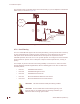
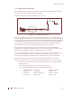
4.2 Routed Mode
In this mode, basic IP routing principles apply. The Ethernet network and the radio network are
divided into separate broadcast domains, as shown in Figure 32 on page 62.
This mode offers greater flexibility in scalability, if the maximum radio network size is planned
in advance. CCU radio networks are assigned to different IP subnets and routed to a gateway
router. This mode offers effective control of Ethernet broadcast domains and added security
over Switched Ethernet mode by isolating subnets.
In Routed mode, it is important to consider the expected network size (taking into account any
future growth) and plan the subnet size accordingly. Changes to the subnet size at a later
stage would require reconfiguration of all the network devices in the radio subnet. The subnet
should be large enough to cater for both the expected number of subscribers and the EUMs.
For example, if the network will be limited to no more than 200 EUMs and about 200 to 300
subscribers (allowing for more than one subscriber per EUM visible to the radio network), then