
User's Manual Part 1

3: Detailed Description
APCD-LM043-8.0 (DRAFT C) 21
3.2 LMS4000 Transmission Concept
This section explains the transmission concept for the following CCU protocol modes:
• Routed Mode on page 21
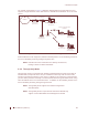
• Switched Ethernet Mode on page 22
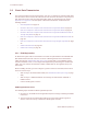
• Through Only Mode on page 23
3.2.1 Routed Mode
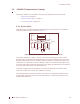
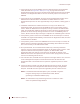
In Routed mode, the LMS4000 900 MHz Radio Network can be thought of as an Ethernet
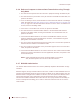
switch with a built-in router, as shown in Figure 12.
Figure 12 LMS4000 Transmission Concept - Routed Mode
In the above diagram, the “switch” consists of the CCU and EUM physical, MAC, and IP
bridging layers, and the 900 MHz link between them. IP packets originating from any host in
the radio subnet (EUM or PC, for example), which are destined for a host that is also in the
radio subnet, are “switched” by the CCU directly to that host. IP packets originating from any
host in the radio subnet, which are destined for a host outside the radio subnet, are “switched”
to the CCU router for routing to the destination host.
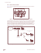
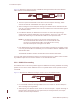
IP packets coming into the CCU Ethernet port, which are destined to a host in the radio
subnet, are routed to the “switch” and “switched” to the host.
In the Routed mode, the Ethernet interface of the CCU is on a different IP subnet than the
“radio” subnet. The latter connects the CCU radio interface, and Ethernet interfaces of all
EUMs & subscribers PCs.
CCU Router
EUM Host
PC
EUM Host
End-user
LAN
PC
EUM Host
CCU Ethernet port
"Switch"
CCU
CCU Application