
User's Manual Part 1


14 APCD-LM043-8.0 (DRAFT C)
3: Detailed Description
3.1 LMS4000 Overview
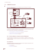
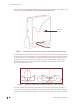
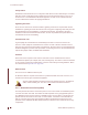
Figure 5 is a high-level schematic of the LMS4000 system, showing the key system
components and interfaces.
Figure 5 LMS4000 System
As shown, each LMS4000 component is associated with one of three major system entities.
Each of these entities is described in the following pages:
• End-user Modem or Customer-premises Equipment on page 14
• Communications Access Point (CAP) on page 18
• Network Access Point (NAP) on page 20
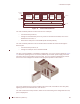
3.1.1 End-user Modem or Customer-premises Equipment
The EUM equipment is installed at the end-user’s premises. It provides an interface to the
customer’s computer or local area network on one side and wireless access to the LMS4000
network on the other.
Key Components
The following components are key to the customer-premises equipment components. Each
component is described on the following pages:
• EUM on page 15
• EUM Antenna on page 15
NMS Station
Router
Internet
EUM
Backhaul (NCL1170,
f or example)
To Other
CAPs
Network and
Equipment
Management
10/100BaseT
-Subscriber
Management
-Billing Data
- Authorization
- Registration
Layer 3
- Switching
- Routing
NAP
CAP
Routing to/from
Internet
EUM
- Authorization
- Registration
UPS
Radio Control
- Configuration
CCU
CCU
CCU
Antenna
Antenna
Antenna
Cavity Filters
Not part of
LMS4000
Switch
10BaseT
End-user PC
EUM
End-user PC
EUM End-user PC