
User's Manual Part 1


94 APCD-LM043-8.0 (DRAFT C)
6: Installation & Diagnostic Tools
ftp> get specan.pdf
local: specan.pdf remote: specan.pdf
200 Port set okay
150 Opening BINARY mode data connection
226 Transfer complete
6394 bytes received in 0.04 secs (171.3 kB/s)
ftp> bye
NOTE: Click here to obtain a copy of Acrobat Reader from the Adobe
Web site.
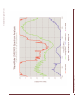
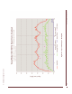
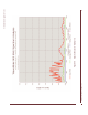
Examples of Spectrum Analyser graphical displays are shown in Figure 44, Figure 45, and
Figure 46.
Figure 44 (Spectral Analysis - Example A) illustrates the spectral analysis from one of three
co-located CCUs, each equipped with a bandpass filter, in a quiet RF environment.
Figure 45 (Spectral Analysis - Example B) illustrates the spectral analysis from an EUM that is
near a site with four co-located CCUs, each equipped with a bandpass filter, in a quiet RF
environment.
Figure 46 (Spectral Analysis - Example C) illustrates a spectral analysis from a CCU, without a
bandpass filter, at an extremely congested RF site. It shows two very large interferers, at the
upper and lower ends of the band. This (actual) installation is running well with more than 20
EUMs at 915 MHz, with a bandpass filter installed.