
User's Manual Part 1


88 APCD-LM043-8.0 (DRAFT C)
6: Installation & Diagnostic Tools
6.1 Indicators and Connectors
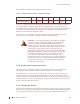
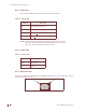
The CCU and EUM are equipped with LED indicators that provide a visual indication of the
status of the unit and its interfaces. The EUM LED indicators are illustrated in Figure 41, the
CCU LED indicators in Figure 42, and a detail view of the Ethernet connector in Figure 43.
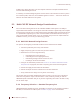
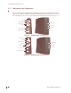
Figure 40 EUM3003 LEDs and Connectors
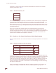
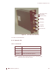
Figure 41 EUM3000 LEDs and Connectors
Network LED
Radio LED
Power LED
Ethernet 10BaseT
INOP Button
Power Connector
Antenna Connector
Traffic LED
Link LED
Network LED
Radio LED
Power LED
Ethernet 10BaseT
Serial Port
Power Connector
Antenna Connector
Traffic LED
Link LED
USB (not used)