
User's Guide


VCom Inc.
BTR5857 Manual; ML_BTR5857_02 (Mar 2004)
Approved: G.C.
15
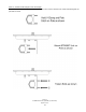
2.4 Connection to CMTS, Power Inserter and Wall Adapter
Connections to the BTR5857 are made as shown in Diagrams 2.3A and 2.4A
Please note:
1) Connect the BTR5857 F-Connector to the power inserter, located indoors with the CMTS. The power inserter is
then connected to the CMTS. The power inserter has three connections:
DC POWER Connect to wall adapter with RG-59 cable with F connectors
TO MODEM Connect to CMTS upstream port
TO TRANSCEIVER Connect to BTR5857
WARNING!
If the power inserter is not correctly connected, the BTR5857 will not operate, and
there is the potential to damage the CMTS.
Ensure that all wires and cables are hooked up before plugging into the AC
adapter/power supply (i.e. hook up to the power supply last).
D
DD
D
IAGRAM
IAGRAM IAGRAM
IAGRAM 2.4A: C
2.4A: C2.4A: C
2.4A: CONNECTION TO
ONNECTION TO ONNECTION TO
ONNECTION TO CMTS
CMTS CMTS
CMTS VIA
VIA VIA
VIA P
PP
POWER
OWER OWER
OWER I
II
INSERTER
NSERTERNSERTER
NSERTER