
User's Manual


VCom Inc.
BST1918 Manual; ml_bst1918_02 (Sept 2005)
Approved: C.H.
11
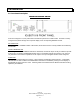
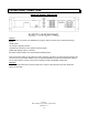
4.0 REAR PANEL CONNECTIONS
D
DD
DIAGRAM
IAGRAM IAGRAM
IAGRAM 4.0
4.04.0
4.0A
AA
A: R
: R: R
: REAR
EAR EAR
EAR P
PP
PANEL
ANEL ANEL
ANEL –
––
– BST1918 S
BST1918 S BST1918 S
BST1918 SYSTEM
YSTEMYSTEM
YSTEM
WM4040
The BST1918 is connected to the WM4040 by a single IF cable connection which carriers the following
signals:
-48VDC power
Low frequency signaling channel
18-42 MHz (or sub-band) for the upstream received signals
90 MHz high stability frequency reference
Sub-band of 555-570 MHz for the downstream-transmitted signal
There is active DC voltage on this cable and caution should be used when connecting and disconnecting the
unit. Be sure to have the IDU disabled in the corresponding WM4040 module when handling this cable. An
over-current shutdown circuit is used to prevent damage to either the WM4040 or BST1918.
ANTENNA
This connector should be tied to the feed cable for the antenna. Both transmit and receive signals are
present on this cable.