
Specifications
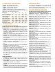

VX16/G3 has 16 three pole relays wired out to a 50 pin header
and is available with Type S, M, or LT reed switches.
VX16/GC has 16 single pole, Form C relays wired out to two 20
pin header connectors as shown in Fig. 6.
These modules are available with Type CS relays.
VX GENERAL PURPOSE MODULES
VX/G SWITCH MODULES
VXC/4X4 COAXIAL SWITCH MODULE
VX/K SWITCH MODULES
VXC/8X2 COAXIAL SWITCH MODULE
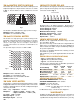
These modules have the inputs of 16 relays wired to header
connectors on the rear edge of the module and the outputs
wired to the motherboard as shown in Figs. 5 & 6.
Plugged into the bussed motherboard, the modules can be wired
in configurations of 16x16, 32x8, 64x4, 128x2 or 256x1.
The following types of modules are available:
VX16/G1 has 16 single pole relays wired to two 20 pin headers
as shown in Fig. 5 and is available with Type S or M reed re-
lays.
VX16/G2 has 16 two pole relays wired to two 20 pin headers as
shown in Fig. 5 and is available with Type S, M or LT reed
relays.
These modules have 16 individual relays with both inputs and
outputs brought out to header connectors on the rear of the
module. There are no connections to the motherboard, and
these modules can be used in any combination with other VX
modules.
There are two types of modules:
VX/KA has 16 Form A relays wired out to two 20 pin header
connectors as shown in Fig. 7. It is available with both Type S
or M reed switches.
VX/KC has 16 Form C relays wired out to a 50 pin header
connector as shown in Fig. 8. It is available with both Type CS
or CM reed switches.
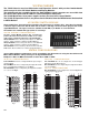
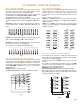
This module has 16 single pole coaxial relays interconnected
by 50 ohm characteristic impedance striplines in an 8x2 matrix
configuration as shown in Fig. 10.
The inputs are wired out to SMA connectors on the rear of the
module.
The outputs are switched through isolation relays to two SMA
connectors on the back panel and to the card edge connector
which plugs into a coaxial motherboard.
Bandpass is DC to 200 MHz (-3dB).
Crosstalk and Isolation are better than 60 dB at 10 MHz.
When plugged into the coaxial motherboard, the bandpass is
dependent on matrix size due to the stub length, and in a 128x2
matrix, the bandpass is 50 MHz.
This module has 16 single pole coaxial relays interconnected
by 50 ohm characteristic impedance striplines in a 4x4 matrix
configuration as shown in Fig. 9. The inputs and outputs are
wired out to coaxial connectors on the rear of the module which
can be SMA, SMB or Coaxicon. There are no connections to
the motherboard.
Bandpass is DC to 400 MHz (-3dB).
Crosstalk and Isolation are better than 60 dB at 10 MHz.
Fig.9
Fig. 10
Fig. 7
Fig. 8
Fig. 6
Fig. 5
0 1 2 3 4 5 6 7 8 9 10 11 12 13 14 15
0 1 2 3 4 5 6 7 8 9 10 11 12 13 14 15
0
1
2
3
4
5
6
7
8
9
10
11
12
13
14
15
0
1
2
3
4
5
6
7
8
9
10
11
12
13
14
15
X0
X1
X2
X3
Y0
Y1
Y2
Y3
VX-3
0
1
2
3
4
5
6
7
8
9
10
11
12
13
14
15
Y0
Y1
X0
X1
X2
X3
X4
X5
X6
X7