
Specifications

The RJB Series are bidirectional, nonblocking, four wire Solid State Matrices and are used to
switch the following signal types: TTL level analog or digital (0-5 volts), 10Base-T or Token
Ring. Each Mainframe is built with integrated power supplies, a Control Module, either an 8x8 or
16x16 Solid State Switch Module and one of three types of built in Interface Modules. The
Interface Modules adapt the solid state switch fabric to the signals that are to be switched.
RJB/8x8 and RJB/16x16 MAINFRAMES
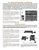
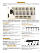
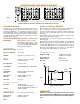
These are 19" rack mounting units, either 1.75" or
3.5" high. (Fig. 8 shows the 1.75" chassis.) Each
chassis is built with the RJB/8x8 or RJB/16x16 Solid
State Switch Module, one Control Module, power
supplies and the appropriate Interface Modules.
Standard connectors are: IDC headers for TTL,
CAT5 RJ45s for Ethernet and 9 Pin D subminiatures
for Token Ring. Other optional connectors can be
specified by the user. Please contact our Applica-
tions Engineers for additional details.
RJB SOLID STATE SWITCH MODULES
The solid state switch fabric is the heart of the matrix
and two standard models are offered: the RJB/8x8 and
the RJB/16x16. These furnish nonblocking, bidirectional
four pole analog switching of 0 to +5 volts signals with a
low path ON resistance of approximately 3 ohms. Band-
pass (-3dB) is DC to 50 MHz at balanced relay and
Crosstalk is -40dB at 20 MHz.
RJB/8x8 SWITCH MODULE
This is an 8x8 four wire solid state matrix. Any one of eight
individual four wire inputs can be connected to one of eight
four wire outputs. Signal inputs and outputs are wired from
two 34 pin IDC header connectors located on the Switch Mod-
ule to the integrated Interface Modules, which also provide
the rear panel connectors.
RJB/16x16 SWITCH MODULE
This is a 16x16 four wire bidirectional matrix. Any one of 16
separate four wire inputs can be switched to any one of 16
individual four wire outputs. Signal inputs and outputs are
wired out from four 34 pin header connectors located on the
Switch Module to the required Interface Modules. The Inter-
face Modules furnish the rear panel signal connectors.
RJB INTERFACE MODULES
The core RJB Solid State Switch Fabric handles TTL
level signals of 0 to +5 volts. The RJB Interface
Modules are an interface between the core Switch
Fabric and the input and output signals that are to
be switched. These Interface Modules enable the
matrix to handle 10Base-T and Token Ring signals.
Each Interface accepts eight input or output sig-
nals, therefore, two are required in the RJB/8x8 Ma-
trix and four are needed in the RJB/16x16.
RJB/M1 INTERFACE
This is used whenever TTL level signals are being switched.
The RJB/M1 essentially provides a hard wired connection
between the RJB/8x8 or RJB/16x16 Solid State Switch Mod-
ule and 34 pin header connectors on the chassis rear panel,
with no signal transformation. Analog Pulse rates of 50 MHz
can be handled by this interface with low crosstalk between
signal paths.
RJB/M2 INTERFACE
This adapts the unit to 10Base-T Ethernet LANs. This inter-
face is built with CAT5 RJ45 rear panel connectors and iso-
lation transformers as required by Ethernet. Bandpass and
Crosstalk meet all 10Base-T Specifications.
RJB/M3 INTERFACE
This is used when Token Ring is to be switched. The mod-
ules supply D9 connectors and transformers as required by
Token Ring Networks. The D9 connector size increases the
chassis height to 3.5".
OPTIONS
Custom Interface Modules can be supplied for switch-
ing other signal types. Please consult our Applications
Engineers.
RJB SERIES SOLID STATE SWITCH MATRICES
Fig. 8 RJB/16x16 Matrix with RJB/M2 Ethernet Adaptor Option
RJ-4