
Specifications
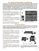
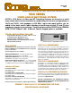

The RJV Series are high performance, bidirectional, passive Multiplexers or Matrices designed
for demanding communication applications such as 100Base-T Network Switching. These units
are built with high sensitivity Type A Armature Relays to insure low signal-to-signal crosstalk.
Exceptional longitudinal balance and low insertion losses are achieved at high data rates. Con-
nectors are CAT5 RJ45. A modularized design is used, and each Mainframe is built with inte-
grated power supplies, a Control Module and a motherboard that holds the RJV Switch Modules.
This results in a great deal of configuration flexibility.
01234567891011
0
Backplane Connection
RJV/48 MAINFRAME
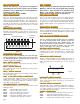
This chassis is 5.25" high and accepts up to four RJV Series
Switch Modules. The modules can be used individually, or they
can be bussed together in several different configurations. As
a 48x1 Mux, Bandpass is 100 MHz at -2dB and Near End
Crosstalk between wire pairs (NEXT) is -42dB at 80 MHz, which
exceeds 100Base-TX network specifications.
Fig. 5
RJV/144 MAINFRAME
This is a 19" rack mounting chassis, 10.5" high and 16" deep
and is designed to hold up to twelve RJV Series Switch Mod-
ules. These can be used individually or bussed together in
several configurations. In all configurations, 100Base-TX Band-
pass and NEXT specifications are met.
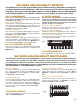
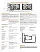
RJV/12x1-4, -8 SWITCH MODULE
Each module supplies a 12x1 Multiplexer as shown in Fig. 5.
Four or 8 pole versions are available. Four modules can be
placed in the RJV/48 chassis to supply four (12x1), two (24x1),
or one (48x1) Mux. In the RJV/144 chassis, one (144x1), two
(72x1), four (36x1), or twelve (12x1) Muxes can be configured
using 12 switch modules.
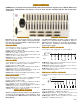
RJV/6x2-4 SWITCH MODULE
These modules switch four poles in a 6x2 Matrix configuration
as shown in Fig. 6. They can be assembled in the RJV/48 as
one (24x2), two (12x2) or four (6x2) Matrices. In the RJV/144 ,
one (72x2), two (36x2), four (18x2) or twelve (6x2) Matrices
can be achieved.
RJV/6x4-4 SWITCH MODULE
These also switch four poles but are configured as a 6x4 Matrix
as shown in Fig. 7. They can be assembled in the RJV/48 to
create one (24x4), two (12x4) or four (6x4) Matrices, and in the
RJV/144 to make one (72x4), two (36x4), four (18x4) or twelve
(6x4) Matrices.
The RJV Switch Modules can be assembled in many differ-
ent ways to provide a number of additional configurations.
Contact our Applications Engineers to discuss your spe-
cific needs.
012 34 5
0
1
Backplane Connections
012 34 5
0
1
2
3
Backplane
Connections
Fig. 6
Fig. 7
RJV SERIES MULTIPLEXERS and MATRICES
Fig. 4 RJV/144 Mainframe - Rear View
RJV/4(1x2)-4, -8 SWITCH MODULE
Each module furnishes four individual 1x2 or "A/B" switches.
Four and 8 pole versions are available. Form C relays are used,
meaning each of the four switches has a Normally Closed posi-
tion. In an RJV/48, four modules will furnish 16 A/B Switches,
and in the RJV/144, 12 modules will give 48 switches.
Four Pole Versions of Switch Modules are shown
RJV/144-E EXPANSION CHASSIS
This is the same as above but is powered and controlled via
a MESA Control Chassis as detailed in the MESA Bulletin.
RJ-3
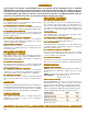
All RJV Switch Modules use high sensitivity, high isolation Type A Armature Relays and CAT5 RJ45
connectors. Up to eight poles can be switched (but not on all models). Signals can be routed to the
Common connectors on the individual modules or alternately to the motherboard bus. The latter inter-
connects the modules and provides larger multiplexers and matrices.
RJV SWITCH MODULES