
Specifications

CL8 DISPLAY MODULES
RJM SERIES HIGH PERFORMANCE MATRICES
These are 19" rack mounting chassis, 3.5" high and 16"
deep. Each Mainframe is assembled with power supplies
and motherboards that hold one Control Module and up to
16 RJM Series Switch Modules. Signal connectors are CAT5
RJ45 jacks. One CL8 Module is required for each Switch
Module. Three different standard matrix configurations are
offered:
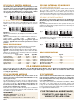
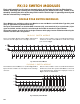
RJM/2(16x4) MAINFRAME
This chassis holds up to 16 RJM/2(1x4) Switch Modules and
forms two separate 16x4 matrices as shown in Fig. 2. Each
matrix has a Bandpass of DC to 30 MHz (-3dB). Crosstalk
between signal pairs is less than -60dB at 20 MHz.
RJM/16x8 MAINFRAME
This mainframe holds a maximum of 16 RJ/2(1x4) Switch Mod-
ules (each jumpered in a 1x8 configuration) to furnish a 16x8
Matrix. Bandpass is DC to 25 MHz and Crosstalk is less than
-50dB at 20 MHz.
RJM/32x4 MAINFRAME
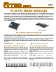
RJM/2(1x4)-4,-8 SWITCH MODULES
These modules are built with high sensitivity two pole Type
A Armature Relays which insures high isolation among sig-
nal pairs. Modules switching either 4 or 8 pins on CAT5
RJ45 connectors are available and are defined by the cor-
responding part number suffix. Each two pole relay
switches one pin pair on the RJ45 jacks as defined in the
EIA/TIA 568 Specification - that is, Pins 1&2, 3&6, 4&5, 7&8.
Built in pin jumpers allow the switch module to be config-
ured as a single 1x8 Matrix as shown in Fig. 3.
One Display Module is required for each RJM Switch Module.
These control the switch module and have LEDs that show
switch status.
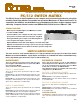
The RJM Series are high Performance, bidirectional, passive Matrices and are designed to switch
high speed communication signals, including T1, E1, DSL and 100Base-T Ethernet. High sensi-
tivity Type A Armature Relays and CAT5 RJ45 connectors are used to ensure that high pair-to-
pair isolation, and CAT5 attenuation and crosstalk specifications are met. A modularized design
is utilized, and each Mainframe is built with integrated power supplies, a Control Module and
prewired Motherboards. CL8 Display Modules show switch point status. The RJM Switch Mod-
ules are available in versions switching from 2 or 4 of the EIA/TIA 568 specification pairs.
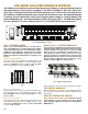
Fig. 2
A
B
Jumpers
0123
45 67
Fig. 3 RJM/2(1x4) Switch Module
012 15
4
5
6
7
0
1
2
3
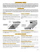
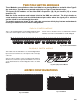
Fig. 1 RJM/16x8 Matrix - Rear View
Relay specifications are shown on the last page of this bulletin.
RJM/128 MAINFRAMES
RJM/128 EXPANSION CHASSIS
These chassis are the same as the mainframes without
power supplies or a control module. They are controlled
and powered by a MESA Control Chassis as detailed in the
MESA Bulletin.
Bussing together the four output pairs (0A & 0B, 1A & 1B, etc)
of the first two 16x4 matrices shown in Fig. 2, creates a single
32x4 matrix with a Bandpass from DC to 15 MHz and Crosstalk
less than -45dB at 20MHz.
RJ-2