
Specifications

RAM OPTION
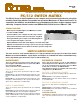
PX-4
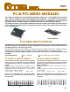
CONTROL MODULES
FOR TECHNICAL ASSISTANCE CONTACT 1-800-346-3117 or
WWW.CYTEC-ATE.COM.
SWITCH SPECIFICATIONS
The Modules and Chassis are available with the following op-
tions selected by the suffix at the end of the Model Number:
CONNECTOR OPTIONS
Power - 100-130 Volts AC or 200-240 Volts AC,
50 to 60 Hz, 100 W.
Environment - Operating Temperature 0
0
to 50
0
C.
Storage Temperature -25
0
to 65
0
C.
GENERAL SPECIFICATIONS
• Bandpass DC to 10 MHz
• Isolation -40dB at 10 MHz
• Crosstalk -40dB at 10 MHz
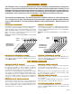
64x8 MATRICES
• Bandpass DC to 20 MHz
• Isolation -40dB at 10 MHz
• Crosstalk -30dB at 10 MHz
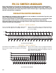
32x16 MATRICES
The Matrices are designed for maximum bandpass and isola-
tion between channels.
All test results are on a full chassis of 16 modules with 50
ohm source and 50 ohm termination.
MATRIX SPECIFICATIONS
Three types of switches are available, the Type S, Type M and
Type LT.
Type S Standard is a dry reed switch for most medium range
applications.
Type M Mercury is a mercury wetted switch for high power
or low contact resistance applications.
Type LT Low Thermal is a dry reed switch for low level ap-
plications with less than 1 microvolt offset.
All switches are guaranteed for 100 million operations when
used within the following specifications:
SOFTWARE
This option is available with the above Control Modules and
with the MESA Control Unit.
Switch selections can be stored in a battery back up RAM so
that the switches can be latched to a preset configuration up
to 1000 switch selections.
After power loss, the switch matrix will reset to the last se-
lected switch configuration.
This Manual Control has a Keypad and LCD Display on the
front panel so that the operator can select any relay and Latch
the Relay or check the Status of the Relay on the Display.
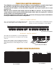
MC-2 MANUAL CONTROL
This Module combines all the features of the RS232 Serial
and IEEE488 GPIB Bus Modules detailed in the Applications
Bulletin AP-5.
IF-5 IEEE488/RS232 COMBINED MODULE
Plug in Modules control the PX/512 Mainframes from the
IEEE488 Bus or the RS232 Serial Port.
The Controls can Select and Latch or Unlatch any Switch
in the Matrix. The controls can also request the Status
of any Switch or can Request the Status of the complete
Matrix.
The cycle time to Select and Latch a relay and obtain
status is 30 msec.
IF-6 LAN INTERFACE
Drivers and/or sample programs are available for the
most commonly available application programming lan-
guages.
VMC VIRTUAL MANUAL CONTROL
This software enables the remote operator to view the Status
of the Matrix using a full Graphical User Interface.
The matrix configuration is displayed and crosspoints are se-
lected by a point and click operation. Each selected cross-
point is prominently shown on the display.
Custom labelling of the Inputs and Outputs can be pro-
grammed.
One optional mode of operation prevents selection of switches
that would interconnect two Inputs or two Outputs.
This module interfaces between the Local Area Network and
the RS232 Control Modules using TCP/IP commands as de-
scribed in the Applications Bulletin AP-5.
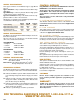
Type S Type M Type LT
Contact Rating 10VA 50VA 10VA
Maximum Switch Voltage 200V 500V 100V
Maximum Switch Current 0.5A 2A 0.2A
Breakdown Voltage 400V 1000V 200V
Operate Time, less than 1ms 2ms 1ms
-N
-H
-S
-W
Indicates the BNC receptacles with isolated shield for two
pole switching and ground shield for single pole switch-
ing.
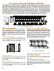
Indicates header connectors, with 16 pin headers for the
single pole modules and 20 pin headers with two wire
plus shield for two pole switching.
Indicates terminal with screw terminal mates which have
two terminals for the single pole modules and three ter-
minals for two pole modules.
Indicates special wiring to customer specification.
WARRANTY
CYTEC Corp. warrants that all products are free from
defects in Workmanship and Materials for a period of
five years and that all switches are guaranteed for their
Rated Operations.