
Specifications

JX-3
JX16/AB SWITCH MODULES
JX16/AB-1 SWITCH MODULE
JX32/AB-1 SWITCH MODULE
Fig. 7
Fig. 8
JX16/AB-4 FOUR POLE MODULE
JX16/PROTO-I/O MODULE
Type P and PC Relays are armature relays for high power
switching with the following specifications:
AC Rating 2000VA
DC Rating 150 W
Maximum Switch Voltage 380Volt RMS
Breakdown Voltage 1000Volt RMS
Maximum Switch Current 8Amp
Operate Time 10msec
Fig. 10
SWITCH SPECIFICATIONS
A/B TYPE MODULE APPLICATIONS
Fig. 9
These Modules typically have 16 relays configured as an
8x2 Matrix so that any of 8 inputs can be switched to either
of 2 outputs. Bandpass is better than 20 MHz (-3dB) and
Isolation is less than 40 dB at 100 kHz when used in a
JX/256 chassis.
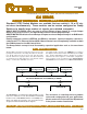
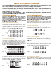
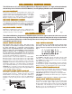
This Module has sixteen single pole relays arranged in an 8x2
configuration so that any of the eight inputs can be switched to
either output A or B as shown in Fig. 7. The eight inputs are
wired to a 16 pin header connector with two pins wired to each
input for convenience in daisy chaining modules. The A and B
outputs are available on a 10 pin header connector, or they can
be bussed to the backplane as shown in Fig. 7. The module is
available with Type S or Type M reed relays.
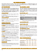
This Module has thirty-two single pole relays arranged in a 16x2
configuration so that any of the sixteen inputs can be switched
to either output A or B as shown in Fig. 8. The sixteen inputs
are wired to a 34 pin header connector with two pins assigned
to each input for convenience in daisy chaining modules, and
two pins are grounds. The A and B outputs are available on a
10 pin header connector, or they can be bussed to the back-
plane as shown in Fig. 8. The module is available with Type S
or Type M reed relays.
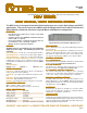
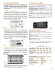
This Module has 16 four pole relays with signal inputs wired to
a 37 pin D type connector as shown in Fig. 9. The outputs A
and B are wired to the edge connector which plugs into the
bussed motherboard. The module is available with Type S or
Type M relays.
Note: This is the only module without Status Feedback.
For Cable, Backplane or Bareboard testing, the requirement is
to select any two points and check for continuity. It is also nec-
essary to check between one point and all others.
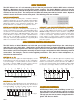
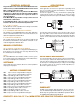
This module, shown in Fig. 10, plugs into the JX Series back-
plane and has logic to control 16 TTL Outputs or Relay Driver
Outputs and 16 TTL compatible inputs.
TTL Outputs are three state, Non Inverting Buffer/Line Drivers
with output capability of 16 LSTTL loads.
Relay Driver Outputs are High Voltage, High Current, Open
Collector Drives with diode suppression for energizing Induc-
tive loads.
Data Inputs are Data Selector/Multiplexers with TTL compat-
ible Inputs and three state output to the JX/256 Mainframe. This
can be used to interrogate the status of the TTL or Relay Driver
Outputs.
Connections may be wired to the 50 pin header supplied on
the module or wired directly to the board.
The following types of relays are available:
Type S are dry reed switches for Instrumentation Level Sig-
nals.
Type LT has a thermal offset of less than 1 microvolt for very
low voltage applications.
Type M has mercury wetted contacts with higher power capa-
bility.
Type CS and CM are form C versions of Type S & Type M.
Type A are two pole armature
All reed switches have a rated life greater than 100 million op-
erations when used within the following specifications:
10 Pin
Header
16 Pin
Header
A Bus
B Bus
Backplane
10 Pin
Header
34 Pin
Header
Backplane
A Bus
B Bus
A Bus
B Bus
37 Pin
D-Type
RELAY TYPE
S< M CS CM A
Contact Rating 10VA 50VA 3VA 25VA 30VA
Switching Voltage 200V 500V 200V 200V 110V
Switching Current 0.5A 1.0A 0.25A 1.0A 1.0A
Carrying Current 1A 2A 1A 2A 1A
Breakdown Voltage 300V 1000V 200V 1000V 750V
Operate Time 1ms 2ms 1ms 2ms 3ms