
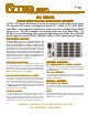
Specifications

CXM MULCXM MUL
CXM MULCXM MUL
CXM MUL
TIPLEXERS and MATIPLEXERS and MA
TIPLEXERS and MATIPLEXERS and MA
TIPLEXERS and MA
TRICESTRICES
TRICESTRICES
TRICES
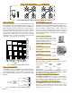
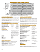
Fig. 2 CXM/64 Mainframe configured as two independent 29x1 Multiplexers
Fig. 3 4x4 Matrix Using Eight CXM/4x1 Switches
Bidirectional NxM Matrices are assembled by interconnecting
the required number of individual microwave switches as
shown in Fig. 3. The matrix is nonblocking, but not full fanout.
Nonblocking means that any input can be connected to any
output without interrupting a previously set path. When a
matrix is not full fanout, an input may be switched to only one
output. Matrix configurations from 2x2 to 8x8 or larger are
possible. The switches and interconnects are assembled
inside the chassis. The input and output connectors (typi-
cally SMAs) are mounted on the rear panel.
1
8
9
16
57
64
C
CXM MACXM MA
CXM MACXM MA
CXM MA
TRICESTRICES
TRICESTRICES
TRICES
CXM MULCXM MUL
CXM MULCXM MUL
CXM MUL
TIPLEXERSTIPLEXERS
TIPLEXERSTIPLEXERS
TIPLEXERS
Standard CXM Switch Modules are bidirectional, failsafe, Nor-
mally Open switches with a bandpass of DC to 18 GHz. Con-
figurations from 1x2 to1x10 are available and SMA connec-
tors are standard. Optional features include: Failsafe de-
fault to port 1 closed, latching actuators, TNC or N connec-
tors, unused input ports terminated to 50 ohms and higher
power handling capability. Standard CXM Switch Modules
are listed below.
SWITSWIT
SWITSWIT
SWIT
CH MODULES SPECIFICACH MODULES SPECIFICA
CH MODULES SPECIFICACH MODULES SPECIFICA
CH MODULES SPECIFICA
TIONSTIONS
TIONSTIONS
TIONS
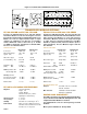
Microwave Switch Specifications vary depending on options.
The following are typical.
1 GHz 18 GHz
Insertion Loss 0.3 dB 0.8dB
Isolation -80dB -60dB
VSWR <1.2:1 <1.5:1
Switching Time <15ms <15ms
Specifications are for switches only. Cableing or connec-
tor options will decrease certian specifications. Call for
specifications on assembled systems.
CXM SWITCXM SWIT
CXM SWITCXM SWIT
CXM SWIT
CH CH
CH CH
CH
MODULESMODULES
MODULESMODULES
MODULES
CXM/6x1-F-SMA
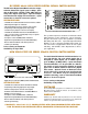
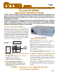
Fig. 4 16x1 Multiplexer using five CXM/4x1 Switches
Nx1 Multiplexers are assembled from standard CXM Chas-
sis by interconnecting microwave switch modules as shown
schematically in Fig. 4. The interconnects are typically semi-
rigid coaxial cables and are wired on the rear panel as shown
in Fig. 2.
CXM/1X2 SWITCXM/1X2 SWIT
CXM/1X2 SWITCXM/1X2 SWIT
CXM/1X2 SWIT
CH MODULECH MODULE
CH MODULECH MODULE
CH MODULE
This is a SPDT Microwave Relay. Op-
tions include connector type, higher power
handling capability and unused port ter-
mination and latching versions.
CXM/1X4 SWITCXM/1X4 SWIT
CXM/1X4 SWITCXM/1X4 SWIT
CXM/1X4 SWIT
CH MODULECH MODULE
CH MODULECH MODULE
CH MODULE
CXM/1X6 SWITCXM/1X6 SWIT
CXM/1X6 SWITCXM/1X6 SWIT
CXM/1X6 SWIT
CH MODULECH MODULE
CH MODULECH MODULE
CH MODULE
This is the same as above, but is a SP6T
configuration.
CXM/1X8 SWITCXM/1X8 SWIT
CXM/1X8 SWITCXM/1X8 SWIT
CXM/1X8 SWIT
CH MODULECH MODULE
CH MODULECH MODULE
CH MODULE
This is the same as above, but is a SP8T
configuration.
CXM/2x1-F-SMA
CL8-CL8-
CL8-CL8-
CL8-
VHP DISPLAVHP DISPLA
VHP DISPLAVHP DISPLA
VHP DISPLA
Y/DRIVER MODULEY/DRIVER MODULE
Y/DRIVER MODULEY/DRIVER MODULE
Y/DRIVER MODULE
The CXM/64 and CXM/128 Chassis require one CL8-VHP per
every eight switch points. These modules control the micro-
wave switches and have LEDs that show switch point status
and are visible through the chassis front panel.
44332211
44
33
22
11
INPUTSINPUTS
OUTPUTS
OUTPUTS
CXM-1
CXM/1X10 SWITCXM/1X10 SWIT
CXM/1X10 SWITCXM/1X10 SWIT
CXM/1X10 SWIT
CH MODULECH MODULE
CH MODULECH MODULE
CH MODULE
This is the same as above, but is a SP10T
configuration.
This is the same as above, but is a SP4T
configuration.
CLE16-CLE16-
CLE16-CLE16-
CLE16-
VHP DISPLAVHP DISPLA
VHP DISPLAVHP DISPLA
VHP DISPLA
Y/DRIVER MODULEY/DRIVER MODULE
Y/DRIVER MODULEY/DRIVER MODULE
Y/DRIVER MODULE
The CXM/256 Chassis require one CLE16-VHP per every 16
switch points. These modules control the microwave switches
and have LEDs that show switch point status and are visible
through the chassis front panel.