
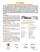
Specifications

+
-
MODULES
COM
It has a Bandpass of DC to
200 MHz with a 4 volt p/p
output and preset gains
from 1 to 16.
Impedances on both inputs
and outputs can be preset
for impedance matching.
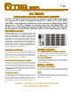
CXBS COAXIAL BUS STRIPS
CX/G AMPLIFIER
The Bus Strips are used to connect between CXR Coaxial Switch
Modules and are designed for maximum bandpass and mini-
mum stub length. They are available to interconnect up to 16
modules. Can not be used with Type G or Type 2A Modules.
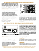
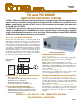
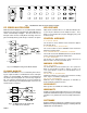
This amplifier has one BNC input and up to 3 BNC outputs. It
can be used to restore signal levels or as a Signal Distributor to
3 Devices, as shown in Fig. 13.
Fig. 13
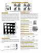
CXR/2x1-2C ( Form C )
A COM B
CXR/2x1-1S or -2S ( Form A )
This module switches a common port
between A, B or OFF positions as
shown in Fig. 9. Module uses single or
two pole, Type S or Type M reed re-
lays. Bandpass is 400 MHz (-3 dB).
Crosstalk is -60 dB at 5 MHz.
CXR/2x1-G ( Form C )
CXR/2x1-GT ( Form A )
Fig. 11
This module is a version of the CXR/
2x1-G module that has the unused
A/B connection terminated into 50 or
75 ohm resistors as shown in Fig 11.
This module allows an off state with
both inputs terminated. It is avail-
able with 50 or 75 ohm impedance.
50 ohm modules use SMA or BNC
connectors
Bandpass is 2.5 GHz (-3 dB).
Isolation is -60 dB at 1 GHz.
75 ohm modules use SMB or BNC
connectors.
Bandpass is 1.5 GHz (-3dB).
Isolation is -60dB at 1 GHz.
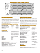
CTC AND CTA A/B SWITCH CHASSIS
CTC and CTA Chassis are designed to control either Form C A/B switches (no off position) or Form A A/
B switches (A, B or Off positions). These chassis are commonly used to sub multiplex larger systems or
act as stand alone fail safe redundancy systems. Systems are configured according to whether they
require one drive per module (Form C versions) or two drives per module (Form A versions). All chassis
are available as Expansion chassis for use with MESA Controllers in larger systems.
CTA CHASSIS
CTC/16 MAINFRAME OR -E EXPANSION CHASSIS
Controls up to 16 form C switch modules. See Drawing Pages
following this bulletin.
CTC/32 MAINFRAME OR -E EXPANSION CHASSIS
Controls up to 32 form C switch modules. See Drawing Pages
following this bulletin.
CTC/64 MAINFRAME OR -E EXPANSION CHASSIS
CTA/32 MAINFRAME OR -E EXPANSION CHASSIS
CTA/64 MAINFRAME OR -E EXPANSION CHASSIS
CTA/128 MAINFRAME OR -E EXPANSION CHASSIS
Controls up to 64 form C switch modules. See Drawing Pages
following this bulletin.
Controls up to 16 form A switch modules. See Drawing Pages
following this bulletin.
Controls up to 32 form A switch modules. See Drawing Pages
following this bulletin.
Controls up to 64 form A switch modules. See Drawing Pages
following this bulletin.
A
B
COM
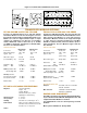
CXR 2x1 (A/B) SWITCH MODULES
The CXR/2x1 Switch Modules may be used in any CXAR or CT Chassis. For large numbers of 2x1's, the
CTA and CTC Chassis listed above should be ordered, but any of the 2x1 Modules may be mixed with 8x1
or 4x1 modules in the chassis listed in previous sections. Please contact CYTEC for labeling options on
chassis that mix multiple module sizes.
This module switches the common to
one of two inputs as shown in Fig. 8.
In the unenergized position, the com-
mon is connected to input A. It is avail-
able with 50 or 75 ohm impedance. 50
ohm modules use SMA, SMB or BNC
connectors
Bandpass is 2.5 GHz (-3 dB).
Isolation is -60 dB at 1 GHz.
75 ohm modules use SMB or BNC con-
nectors.
Bandpass is 1.5 GHz (-3dB).
Isolation is -60dB at 1 GHz.
A two pole 2x1, Form C configura-
tion as shown in Fig. 10 which allow
one input to be switched to two out-
puts (A or B). Available with BNC or
Twin BNC connectors, and uses
Type A, Armature relays.
Fig. 8
A COM B
A COM
B
Fig. 9
Fig. 10
Fig. 12
CXBS/8 Bus Bar
shown in drawing
CTC CHASSIS
CXAR-4