
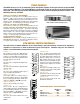
Specifications
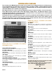
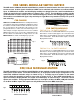

The CXAR Units are 19" rack mounted chassis, and are avail-
able as either Mainframes or Expansion Chassis pre-wired to
accept any of the CXR Series of Coaxial Switch Modules. All
chassis have front panel LED indication of latched switch points
and have the switch modules mounted through the rear panel.
The CT Units are the same but accept 2x1 modules only and
are described on the last page.
The CXAR and CT Series are Computer Controlled Coaxial Switching Systems for High Fre-
quency Signals up to 1.6 GHz. These systems are typically used to configure 1xN multiplexers.
Pre-wired Mainframes and Expansion Chassis will accept a variety of control and switch mod-
ules to form the desired configuration.
CXAR AND CT SERIES
COAXIAL SWITCHING SYSTEMS
CXAR/32 Mainframe
2555 Baird Road, Penfield, New York 14526 (585) 381-4740 FAX (585) 381-0475
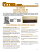
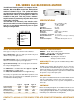
LED DISPLAYS
MANUAL CONTROL OPTION
CONTROL MODULES
FOR TECHNICAL ASSISTANCE, CONTACT 1-800-346-3117 or WWW.CYTEC-ATE.COM
FEATURES:
BULLETIN
CXAR & CT/7
• Bandpass from DC to 1.6 GHz with low crosstalk.
• Computer Control from IEEE488 BUS, RS232 Serial,
and 10BaseT LAN.
• Front Panel Display and Status Feedback to Computer.
• Manual Control Option.
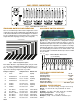
CHASSIS
SWITCH MODULES
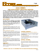
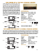
There are three series of Modules all using relays interconnected
by striplines to give the required characteristic impedance for
high bandpass.
CXR Series use coaxial reed relays and are available with a
bandpass up to 300 MHz.
CXR-G Series use armature relays in a tree configuration and
have a bandpass exceeding 1 GHz.
CXR-2A Series use a two pole armature relays to switch bal-
anced line signals and have bandpass up to 200 MHz.
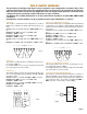
SWITCH CHARACTERISTICS
CXR Modules are available with Standard Reed Type S or Ter-
minating Reed Type T relays.
CXR-G Modules use High Power Armature Type G relays.
CXR-2A Modules use Two Pole Armature Type 2A relays.
Type S Type T Type G Type 2A
Contact Rating 10VA 3VA 24VA 60VA
Switch Voltage 200V 200V 24V 110 V
Switch Current 0.5A 0.25A 1.0A 1.0A
Breakdown Voltage 400V 200V 1000V 750V
Operating Time 1ms 1ms 10ms 3 ms
Life Expectancy* 10
8
10
8
10
7
2x10
5
Manual Controls are available for all chassis types.
CXAR/16 and CTC/16 Chassis utilize momentary pushbutton
manual controls MC/16.
CXAR/32, /64 and /128, CTA/32, /64, /128, CTC/ 32, and /64
chassis utilize Thumbwheel Manual Controls MC/32, /64 and
/128 respectively.
IF-3B or 3C RS232 CONTROL MODULE
This Module has all the RS232 features detailed in Applica-
tions Bulletin AP-5. The IF-3B is used on 16 channel chassis.
The IF-3C is used on 32 channel chassis.
IF-4B or 4C IEEE488 BUS (TALK/LISTEN)
This Module has all the IEEE488 features detailed in Applica-
tions Bulletin AP-5. The IF-4B is used on 16 channel chassis.
The IF-4C is used on 32 channel chassis.
IF-5 IEEE488/RS232
This Module has both the IEEE488 (Talk/Listen) and the RS232
features detailed in Applications Bulletin AP-5. This combina-
tion module is used on all 64 or 128 channel chassis.
IF-6 LAN INTERFACE
This Module uses TCP/IP to allow control from a Local Area
Network as described in AP-5. It is available as an option on
any unit with RS232 Control.
CXAR/16, CT/16 and CT/32 Chassis include front panel LED
display of switchpoint status. CXAR/64, CXAR/128, CT/64 and
CT/128 Chassis require one separately purchased CL8 Dis-
play module for each eight switch points. This LED indication
is an invaluable aid in program debugging and determining sys-
tem status.
CXAR-1
*Life expectancy is at rated load
VMC VIRTUAL MANUAL CONTROL SOFTWARE
VMC Software allows the switches to be controlled through a
Graphical User Interface. Current version is Windows based.
Free with any system purchase.