
Specifications
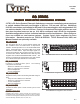
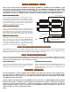

INTERFACE BULLETIN AP-5
BULLETIN
AP-5
CONTACT 1-800-346-3117 OR CYTEC-ATE.COM FOR TECHNICAL ASSISTANCE
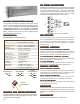
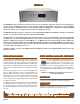
GX-3
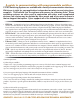
Mainframe Control Modules Mesa Control Modules (Large systems)
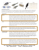
IF-5, IF-5C
-- IEEE488 / RS232 Combination.
IF-9 -- 100BaseT Ethernet LAN/RS232 Combination.
IF-6 -- 10BaseT to RS232 converter used in conjunction with
IF-5 controls to give all three possible interfaces or combinations
of GPIB and LAN. Can be added externally to existing units.
IF-7 -- USB to RS232 adapter. Inexpensive way to update legacy
RS232 systems to USB ports.
IF-1 -- TTL Control Module - 13 bits of input and 1 bit of out-
put. Lo true logic with D25 connector.
CM-5 -- IEEE488 / RS232 Combination.
CM-8 -- 100BaseT Ethernet LAN/RS232/GPIB Combination.
IF-6 -- 10BaseT to RS232 converter used in conjunction with
CM-5 control to give all three possible interfaces or combinations
of GPIB and LAN. Can be added externally to existing units.
IF-7 -- USB to RS232 adapter. Inexpensive way to update legacy
RS232 systems to USB ports.
CM-1 -- TTL Control Module - 13 bits of input and 1 bit of
output. Lo true logic with D25 connector.
See next page for a guide on which one to chose.
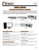
QUICK GUIDE - Call or E-mail for complete manuals.
All Cytec systems and interfaces speak the same language and use the same simplistic command set. ere are
additional commands for more complicated systems that you may or may not make use of but the basic syntax is
the same for every system we have ever made over 32 years. It's just a switch, we try to keep it simple.
All Cytec commands consist of an alpha character or characters followed by two or three integers. e alpha character is
the command and the integers are the programmatic address of the relay. If you have a single chassis Mainframe the two
integers are the module # followed by the relay or switch #. If you have a matrix con guration such as a 16x8 con guration
the integers will typically correspond to an input or output number.
Commands:
L = Latch = Close Relay or turn ON relay.
U = Unlatch = Open Relay or turn OFF relay.
C = Clear = open all relays or turn OFF all relays
S = Status which can be used on individual switch points, modules, or the entire system.
e S command returns a 1 for on (Latched) and a 0 for OFF (Unlatched)
ex:
e command L3 5 translates to Latch Module #3, Relay # 5 or turn on relay #5 on module #3.
e command U7 14 translates to Unlatch Module #7, Relay #14 or turn o relay 14 on mod 7.
e command S4 returns 00100000 Where module 4 has 8 relays.
which translates to "the third relay on Module #4 is ON, all others are OFF.
If the system has multiple chassis you simply add the chassis # as the leading integer, i.e:
L3 10 25 = Latch Chassis #3, Module #10, Relay #25 or Turn on relay 25 on module 10 in chassis 3.