
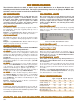
Specifications
MESA-3
Command Summary
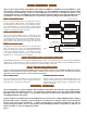
L - Latch - a specified Module and Switch in a Matrix.
U - Unlatch - a specified Module and Switch in a Matrix.
X - Multiplex - While in MUX mode, latches a specified
Switch and Clears all others.
C - Clear - Unlatches every switch and clears interface.
S - Status - The Status of all switches is returned to the
Controller.
F - Front Panel - Allows the disabling/enabling of front
panel controls.
P - Program - Allows the operator to set up Matrix vari-
ables such as size and configuration and stores them in
nonvolatile memory.
Typical Commands Are:
Command Function
L, n1, n2, n3 Latch Selected Switch
U, n1, n2, n3 Unlatched Selected Switch
X, n1, n2, n3 Mux Selected Switch
n1=Matrix, n2=Module, n3=Switch
C Clear entire system
C, n1 Clear matrix - n1=Matrix
S Status of Entire System
S, n1 Status of Matrix - n1=Matrix
S, n1, n2, n3 Return Switch Status
n1=Matrix, n2=Module, n3=Switch
F, n1, n2, Front Panel Lock out
n1=0 disable, n1=1 enable, n2=access
P, n1, n2, n3 Program setup
n1=Parameter, n2=value, n3=access
RS232 SERIALRS232 SERIAL
RS232 SERIALRS232 SERIAL
RS232 SERIAL
The module can be configured as either a Data Terminal
Equipment (DTE) or Data Communications Equipment
(DCE). The Baud Rate is software programmable from 110
to 19,200 Baud and is stored in nonvolatile memory.
The Command structure is the same as the IEEE488 Mod-
ule and has the following additional command features:
E - Echo - Echoes all received characters back to the source.
V - Verbose - Enables the matrix to return text strings in re-
sponse to Commands, including error statements.
H - Help - This is a summary of all Commands.
RS232 Specific Commands
Command Function
B, n1, n2 Baud Rate - n1=rate, n2=access
E, n1, n2 Echo - n1=0 off, n1=1 on, n2=access
V, n1, n2 Verbose - n1=0 off, n1=1 on, n2=access
IF-6 LAN INTERFIF-6 LAN INTERF
IF-6 LAN INTERFIF-6 LAN INTERF
IF-6 LAN INTERF
AA
AA
A
CECE
CECE
CE
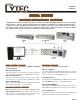
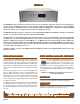
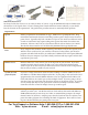
The LAN Interface accepts TCP/IP packets from a 10BaseT
Ethernet Network, converts the data into RS232 format, and
then transmits it to the RS232 port located on the standard
CM-5 Control Module installed in the MESA. Data is also trans-
mitted in the reverse direction; that is, RS232 data from the
MESA is converted and sent over the Ethernet LAN. The com-
mand structure is the same as shown for the CM-5. In the
MESA 16 & 32, the LAN must be used with the CM-5. The
LAN Interface allows several users to access the MESA re-
motely via Ethernet TCP/IP and also via TELNET. The IF-6 is
set up via an external RS232 connection that allows the user
to specify IP Address, host name, gateway and many other
network parameters.
CM-5 IEEE488/RS232CM-5 IEEE488/RS232
CM-5 IEEE488/RS232CM-5 IEEE488/RS232
CM-5 IEEE488/RS232
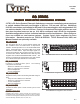
This Module installs with the MESA 16 & 32 and combines
both IEEE488 Talk Listen and RS232 Serial Controls.
The Talk and Listen addresses are the same and are set by
a 5 position DIP Switch. In the Listen Mode, the Matrix re-
sponds to specific commands. The Talk Mode is used to
return the Status of the Matrix.
IEEE488 TIEEE488 T
IEEE488 TIEEE488 T
IEEE488 T
ALK/LISTEN (GPIB)ALK/LISTEN (GPIB)
ALK/LISTEN (GPIB)ALK/LISTEN (GPIB)
ALK/LISTEN (GPIB)
RAM OPTIONRAM OPTION
RAM OPTIONRAM OPTION
RAM OPTION
This option is available for the CM-5 and CM-8. Switch selec-
tions are stored in the battery backup RAM (Random Access
Memory) with the following benefits:
-
-
-
At Power On, switches can be set to a preset default configu-
ration.
In cases of momentary power loss, the matrix will be reset to
the last selected configuration when power returns.
Several configurations can be stored and recalled as required,
up to a maximum of 1,000 switch selections.
CM-8 CONTROL MODULECM-8 CONTROL MODULE
CM-8 CONTROL MODULECM-8 CONTROL MODULE
CM-8 CONTROL MODULE
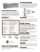
The CM-8 installs in the MESA II Control Chassis ONLY and
has three remote control interfaces: RS232 via a D9 connetor,
IEEE488 Talk/Listen and 100BaseT Ethernet via a RJ45 45
port. All interfaces can be active at the same time. As an
option, two CM-8’s can be installed in the MESA II, with one
Control Module designated the Primary and the second desig-
nated as the Secondary controller. The control modules are
also hot swappable, meaning the can be removed and then
replaced without shutting down the MESA or the full switching
sytem. Network parameters can be set up via any of the
remote interfaces.
Control is via the same commands shown in the CM-5 Control
Module section.
CYTEC SWITCYTEC SWIT
CYTEC SWITCYTEC SWIT
CYTEC SWIT
CH MANACH MANA
CH MANACH MANA
CH MANA
GER SOFTWGER SOFTW
GER SOFTWGER SOFTW
GER SOFTW
AREARE
AREARE
ARE
Using this Software, the remote operator can control and moni-
tor the Status of any Cytec switching system via a full Graphi-
cal User Interface (GUI) installed on the controlling PC. The
switching configuration is graphically displayed, and switch
crosspoints are selected via point-and-click operations. Each
selected crosspoint is prominently displayed.
MCMC
MCMC
MC
-2 KEYP-2 KEYP
-2 KEYP-2 KEYP
-2 KEYP
AD CONTROLAD CONTROL
AD CONTROLAD CONTROL
AD CONTROL
This option supplies a Keypad and LCD backlit display that
mounts on the MESA’s front panel. The LCD Display shows
two lines of 16 characters each. The top line displays entered
Commands and switch selections, while the bottom line dis-
plays switch Status and Error Messages.
The MC-2 is used with the CM-5 and CM-8 Control Modules
and can be installed on the MESA 16, 32, and MESA II Chas-
sis .
MANUMANU
MANUMANU
MANU
AL CONTROL OPTIONSAL CONTROL OPTIONS
AL CONTROL OPTIONSAL CONTROL OPTIONS
AL CONTROL OPTIONS
Two Manual Controls are offered for the MESA: The MC-
2 Keypad and the Switch Manager Software.