
Specifications
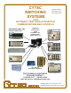
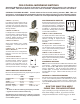

CXM CHASSIS
The CXM Series are 19" rack mounting chassis with built in power supplies and are designed to
hold the CXM Microwave Switches selected by the user. The switches are typically mounted so
that their RF connectors protrude through the rear panel. The front panels have discrete LEDs
showing the status of all switch points. The front panels also hold the optional manual controls.
CXM-2
FOR TECHNICAL ASSISTANCE, PLEASE CONTACT CYTEC AT
800-346-3117 OR VISIT OUR WEBSITE AT cytec-ate.com
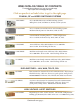
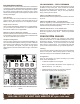
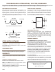
Fig. 1 4x4 Matrix Using Eight CXM/4x1 Switches
Bidirectional NxM Matrices are assembled by interconnecting the
required number of individual microwave switches as shown in
Fig. 1. The matrix is nonblocking, but not full fan-out. Nonblock-
ing means that any input can be connected to any output without
interrupting a previously set path. When a matrix is not full fan-
out, an input may be switched to only one output. Matrix con-
gurations from 2x2 to 8x8 or larger are possible. The switches
and interconnects are assembled inside the chassis. The input
and output connectors (typically SMAs) are mounted on the rear
panel. Unidirectional full fan-out systems and bidirectional full
fan-out systems are also available. Just call and ask.
CXM MATRICES
44332211
44
33
22
11
INPUTSINPUTS
OUTPUTS
OUTPUTS
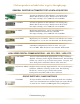
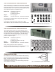
CXM/64 MAINFRAME OR -E EXPANSION CHASSIS
These Chassis control up to 64 switch points as dened by the user.
Front panel LEDs indicate both switch point and power status. Add
controls, the required CXM switches and one CL8-VHP Display
module for every eight switch points to complete the system.
Dimensions:
19" Rack Mount (483 mm)
15" deep (381 mm)
5.25" (3 RU) or 7" (4 RU) high if needed for relays.
Weight: 25 lbs (11 kg) max
AC Power :
10 W per closed switch- 115/230 VAC selectable
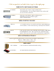
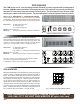
CXM/64 with IEEE488, RS232 & LAN Control
CXM/16 & 32 MAINFRAME or -E EXPANSION CHASSIS
These Chassis furnish either 16 or 32 switch points in user dened
congurations. Built-in front panel LEDs show switch and power sta-
tus. Add CXM switches along with controls to complete the system.
Dimensions:
19" Rack Mount (483 mm)
15" deep (381 mm)
3.5" (2 RU) high (89 mm)
Weight: 15 lbs (6.8 kg) max.
AC Power :
10 W per closed switch- 115/230 VAC selectable.
CXM/32 with IEEE488, RS232 and LAN Control
1
2
3
4
5
6
C
I
O
1
2
3
4
5
6
C
1
2
3
4
5
6
C
1
2
3
4
5
6
C
A/C - IN
IEEE-488
UTP
LINK
MOD 0MOD 1MOD 2MOD 3
RS-232
Up to 64 1x2 relays, 16 1x4 relays or 8 1x8 relays per chassis.
Up to eight, 8 bit programmable attenuators.
Combinations, specials and custom systems with no NRE.