
Specifications
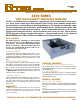

JX-4
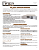
CONTROL MODULES
IF-J1 16 BIT TTL PORT
IF-J5 COMBINED IEEE488/RS232 MODULE
MC-2 MANUAL CONTROL WITH DISPLAY
APPLICATIONS
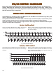
KELVIN BRIDGE MEASUREMENTS
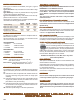
Fig. 12
Fig. 13
Plug in modules can control the JX/256 Mainframe from
either TTL Port, Combined IEEE488 BUS / RS232 Serial
BUS or 10Base-T Ethernet LAN.
The Control Module selects any switch in the Mainframe
and Latches or Unlatches the switch in either the Matrix
or Multiplexer Mode and can also request the Status of
selected switches.
In the Matrix Mode, any number of relays can be selected
and Latched or Unlatched.
In the Multiplex Mode, only one relay is selected and
Latched. All others are automatically Unlatched.
This Module has 16 TTL compatible lines for Relay Select, Mode
Select, Status Switch and Strobe.
This Module has both IEEE488 BUS Control with Talk/Listen
features and RS232 Serial Control. The Control Functions are
detailed in Applications Bulletin AP-5.
IF-6 LAN/RS232 INTERFACE
This module interfaces between the Local Area Network and
the RS232 Control Modules using TCP/IP commands as de-
scribed in Applications Bulletin AP-5.
This Manual Control Option has a Keypad and LCD Display on
the front panel. The operator can select any switch and verify
the switch Status via the display.
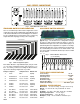
MATING CONNECTORS
J4C 4 pin connector using individual crimp pins
J8C 8 pin connector using individual crimp pins
J10R 10 pin IDC type ribbon cable connector
J10C 10 pin connector using individual crimp pins
J16R 16 pin IDC type ribbon cable connector
J16C 16 pin connector using individual crimp pins
J20R 20 pin IDC type ribbon cable connector
J20C 20 pin connector using individual crimp pins
J34R 34 pin IDC type ribbon cable connector
J34C 34 pin connector using individual crimp pins
J37R 37 pin D type ribbon cable connector
J37C 37 pin D type crimp pin connector
J50R 50 pin IDC type ribbon cable connector
J50C 50 pin connector using individual crimp pins
Fig. 11
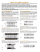
In this application, the Scanner is required to sequentially select
any one of a number of inputs and switch it to a measuring in-
strument such as a DVM.
For low level signals, or in noisy environments requiring high
common mode rejection, it is advisable to use two pole relays
switching both the Hi and Lo input of the DVM as shown in Fig.
11.
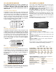
For extremely low level signals such as thermocouples, the LT
type relays with less than 1 microvolt of thermal offset should be
used. For additional noise prevention, the shields from the pairs
of wires can be switched to the Instrument Guard as shown in
Fig. 12.
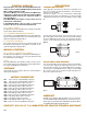
For very low impedance measurements using a four wire bridge,
it is necessary to switch both Stimuli and Sense lines to each
side of the device under test as shown in Fig. 12. This requires
a total of 4 poles switching with two pole relays as shown in Fig.
13. Any two points can be selected, and the impedance be-
tween these points measured.
VMCS
This Virtual Manual Control Software enables a remote opera-
tor to view the Status of the Matrix and to Control Switch Selec-
tion using a full Graphical User Interface.
DVM
HI
LO
DVM
HI
LO
GUARD
BRIDGE
+
-
STIMULUS
+
-
SENSE
MANUAL CONTROLS
CONTACT 1-800-346-3117 or WWW.CYTEC-ATE.COM FOR TECHNICAL ASSISTANCE
CYTEC Corp. warrants that all products are free from de-
fects in workmanship and materials for a period of 5 years.
Reed relays are guaranteed for 100 million operations when
used within their published specifications.
WARRANTY
SCANNER/MULTIPLEXERS
SOFTWARE
Visit our website for free software, drivers for common platforms
and program expamples.