
Specifications
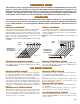

MATING CONNECTORS
J3 - Three pin crimp type header connector.
J3ST - Three screw terminal type header connector.
J20-R - Twenty pin ribbon type header connector.
J20-C - Twenty pin crimp header connector.
J50-R - Fifty pin ribbon cable type header connector.
J50-C - Fifty pin crimp type header connector.
CABLES
CBL-0.5 IEEE488 Cable .5 meters long.
CBL-1 IEEE488 Cable 1 meter long.
CBL-2 IEEE488 Cable 2 meters long.
RS-1 RS232 Cable 2 meters long.
Cables and wired chassis can be built to customers specific
requirements. Please contact our Sales Staff for more informa-
tion.
CHASSIS SLIDES
CHS-1 Pairs of 19" rack mounting chassis slides with 15"
travel.
CABINETS
Portable cabinets with handles for 19" rack mounted units with
10.5" panel spaces and 21" depth.
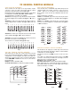
MANUAL CONTROLS
This manual control consists of thumbwheels and toggle
switches on the front panel for switchpoint and mode selection.
A Strobe pushbutton enters the data.
These controls can be "locked out" by the computer.
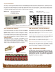
CONTROL MODULES
DIMENSIONS - 19" Rack Mounting, 5.25" high and 12" deep.
WEIGHT - With full complement of Modules - 25 lbs.
POWER - 100-130 Volts AC or 200-240 Volts AC 50-60 Hz, 100
VA.
ENVIRONMENT - Operating at 0
0
C to 50
0
C.
Storage at -25
0
C to 65
0
C.
WARRANTY
CYTEC Corp. warrants that all products are free from defects in
Material and Workmanship for a period of 5 years and that all
switches are guaranteed for their Rated Operations.
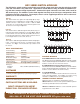
The relays use high reliability reed switches with a guaranteed
life of 100 million operations when used within the following
specifications:
Type S and CS Standard switches are for general purpose in-
strumentation level signals.
Type M and CM Mercury switches are for higher power switch-
ing.
Type LT Low Thermal switches have offset of less than one
microvolt for very low signal level measurements.
GENERAL SPECIFICATIONS
M/256 MANUAL CONTROL
VX SERIES RELAY SPECIFICATIONS
ACCESSORIES
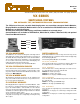
VX-4
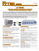
VMCS VIRTUAL MANUAL CONTROL SOFTWARE
This Software displays a full Graphical User Interface (GUI) on
the controlling computer. The operator controls the Mainframe
with simple mouse point-and-click operations. The software can
also be used to control the unit over a LAN.
Windows based software is free with any purchase.
A demo version is available on our web site at:
http://www.cytec-ate.com/soft.htm
IF-1 PARALLEL PORT
This module requires 14 individual TTL level binary lines from
the controlling computer. These select Switch and Mode, Strobe
the selected command and return switch point Status.
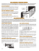
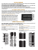
GX GROUP SWITCH
VX16/G2 & VX16/G3 Switch Modules can be used in the
GX/16 Group Switch Chassis to switch signals in groups
of up to 48 wires in up to a 16x1 Multiplexer configuration.
For more information see GX Bulletin.
CONTACT 1-800-346-3117 OR WWW.CYTEC-ATE.COM FOR TECHNICAL ASSISTANCE
The VX Mainframes can be computer controlled via the mod-
ules listed below. Each Control Module selects any
switchpoint and Latches, Unlatches and returns Status of
that point.
This module combines both the IEEE488 Talk/Listen and the
RS232 features detailed in the AP-5 Bulletin.
IF-5 IEEE488/RS232
IF-6 LAN INTERFACE
This module allows control via a 10Base-T Ethernet LAN using
TCP/IP protocol detailed in the AP-5 Bulletin.
SPECIFICATIONS S M LT CS CM
Contact Rating VA 10 50 10 3 30
Switching Voltage DC 200 500 100 200 350
Switching Current DC .5A 1.0A .25A .25A 1.0A
Carrying Current DC 1.0A 2.0A 1.0A 1.0A 2.0A
Breakdown Voltage DC 400 1000 400 200 1000
Operate Time MSec 1 2 1 1.5 3
CUSTOM SYSTEMS
Drivers and Sample Programs are available for the most com-
mon programming languages. These check the entire system
by cycling through all switches, sequentially latching and un-
latching each switch while checking Status.
SOFTWARE
CYTEC Corp. can build Group Switches using a variety of
Switch Modules, Connectors or mixtures of signal types. If
you do not see what you need for your application, please
contact us and give us the opportunity to recommend a solu-
tion.