
Specifications
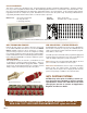
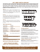
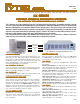
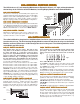
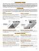
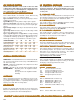
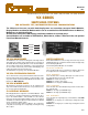
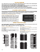
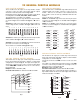

Fig. 3
VX/256 CHASSIS
The VX/256 Chassis consist of Mainframes and Expansion Chassis with pre-wired motherboards
which accept 16 of the VX Switch Modules and Display Modules.
The motherboards are assembled so that the Switch Module signal connectors are accessible from
the chassis back panel and the LEDs are visible through the front panel.
The VX/256 Mainframes have power supplies and are pre-wired for a Control Module.
The VX/256-E Expansion Chassis are powered and controlled from the MESA Control Unit detailed
in MESA Bulletin.
VX MATRIX SWITCH MODULE
SWITCH MODULE CONFIGURATIONS
MATRIX CONFIGURATIONS
These modules have 16 two pole relays arranged as four 1x4 matrices as shown in Fig. 1. One side of each matrix
is wired to signal connectors and the other side is wired to card edge connectors which plug into the VX/256
Signal Motherboard. The signal connectors available include BNC, 3 pin Header or Screw Terminals.
The modules are available with Type S, M or LT reed relays.
The basic Switch Module shown in Fig. 1 includes bus
points A, B and C which allows the module to be config-
ured as either a VX/4(1x4), VX/2(1x8) or VX/1x16 Module.
VX/4(1x4) Module has no bussing and configures as four 1x4
matrices. Allows formation of 4x4 through 64x4 Matrices.
VX/2(1x8) Module is bussed at points A & C to form two 1x8
matrices. Allows formation of 2x8 through 32x8 Matrices.
VX/1x16 Module is bussed at bus points A, B & C to form one
1x16 matrix. Allows formation of 1x16 through 16x16 Matrices.
Fig. 1
Fig. 4
Four 16x4 Matrices can be configured without any bussing as
shown in Fig. 2.
Two 32x4 Matrices can be configured by bussing between Ma-
trices 1 & 2 and between Matrices 3 & 4 in Fig. 2.
One 64x4 Matrix can be configured by bussing between Matri-
ces 1, 2, 3 & 4 in Fig.2.
Several different Matrix configurations can be assembled in the VX/256 Chassis using the three different VX
Matrix Switch Modules and by bussing on the Signal Motherboard.
Bandpass is DC to 10 MHz and Isolation is better than -60dB at 1 MHz.
VX/4(1x4) CONFIGURATIONS
Two 16x8 Matricess can be configured as shown in Fig. 3
without bussing the Motherboard.
One 32x8 Matrix can be configured by bussing between Matri-
ces 1 & 2 in Fig. 3.
VX/2(1X8) CONFIGURATIONS
VX/1x16 CONFIGURATIONS
One 16x16 Matrix can be configured as shown in Fig. 4 with-
out bussing the motherboard.
Fig. 2
0
1
2
3
A
B
C
012
4
5
6
7
0
1
2
3
14 15
8
9
10
11
12
13
14
15
012
0
1
2
3
14 15
0
1
2
3
0
1
2
3
0
1
2
3
1
2
3
4
012
4
5
6
7
0
1
2
3
14 15
012
4
5
6
7
0
1
2
3
14 15
1
2
VX-2