
Specifications

SPECIFICATIONS AND BUFFER OPTIONS
POWER
AC Input Selectable 110 /220 Volt Input.
100 to 130 VAC / 200 to 240 VAC
110 VAC fused @ 3 amps
220 VAC fused @ 2 amps
50 to 60 Hz.
Consumption 200 Watts, 128x128 with ±4V buffers
DC Supply Type Low Noise Linear
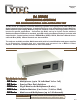
TX SERIES MATRIX
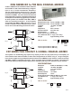
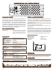
TX/128x128 Mainframe Rear View
with IEEE488, RS232 and LAN
Control
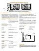
INPUT and OUTPUT BUFFERS
Optional Buffers are available for all Input and/or Output Chan-
nels. These buffers serve up to three different purposes:
1) They transform impedances to allow the solid state switch
fabric to be used for systems with other than 75 ohms character-
istic impedance.
2) Input Buffers can be used to reduce signals to levels where
they can be safely switched by the matrix.
3) Output Buffers can have preset gains to boost signals to re-
quired voltages.
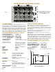
Rout
Rf
Rg
Ri
IN
Rs
OUT
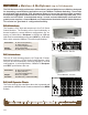
A typical buffer is shown schematically in Fig. 3. Resistors Rs and
Ri set the input impedance and also attenuate the input signal (if
needed), while Rout determines the output impedance. The cir-
cuit is typically built with one of several standard small signal Op
Amps, but custom amplifiers are also possible. The specifica-
tions for a typical small signal amplifier are shown below.
Characteristic Impedance: 50 or 75 Ohms
Small Signal Bandpass (±1.0 V) 140 MHz (±1.5dB)
Large Signal Bandpass (±4.0 V) 75 MHz (-3dB)
Crosstalk: non adjacent path -75 dB @ 20 MHz
adjacent path -47 dB @ 10 MHz
Input/ Output Isolation: -80 dB @ 10 MHz
Switching Speed: 50 ns + Control Interface Delay
Input or Output Buffer
Fig. 2
Fig. 3
TX-2
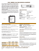
The TX Series is intended to switch small signal levels in a non-
blocking (any input to any output), full fan out (any input to any or all
outputs) configurations. For a 128x128 non blocking three stage
matrix mainly consist of an input, center and output stage. Each
Input stage is a 8x16 matrix. Sixteen input stages gives you 16x8
= 128 input connectors. Each Center stage is a 16x16 Matrix.
There are 16 intermediate stages. Each Output stage is a 16x8
Matrix. Sixteen outputs give you a 16x8 =128 output connectors.
TX SPECIFICATIONS (signal w/o buffers)
TX SPECIFICATIONS (signal with buffers)
Characteristic Impedance: 75 Ohms
Small Signal Bandpass (±0.1 V) 140 MHz (-3dB)
Large Signal Bandpass (±1.0 V) 80 MHz (-3dB)
Crosstalk: non adjacent path -75 dB @ 20 MHz
adjacent path -47 dB @ 10 MHz
Input/ Output Isolation: -80 dB @ 10 MHz
Switching Speed: 50 ns + Control Interface Delay
CONNECTIONS
GENERAL SPECIFICATIONS
Dimensions 19" Rack Mount
10.5" tall (6U) and 20.5" deep
Weight 25 lbs +.7 lbs per input /output module
Full 128x128 =36.2 lbs (16.5 Kg)
Operating Temperature 0
o
to 70
o
C
Storage Temperature -25
o
to 80
o
C
Humidity 95% RH noncondensing to 30
o
C
Signal Connections: SMB, Patch panels normally
provided to convert SMB to
BNC, SMA or customer speci
fied connector.
AC Input: Universal, US Standard AC
RS232: D9 Male
GPIB: IEEE488
10BaseT LAN: RJ45
LAN to RS232: RJ45