
Specifications

FOR TECHNICAL ASSISTFOR TECHNICAL ASSIST
FOR TECHNICAL ASSISTFOR TECHNICAL ASSIST
FOR TECHNICAL ASSIST
ANCEANCE
ANCEANCE
ANCE
, PLEASE CONT, PLEASE CONT
, PLEASE CONT, PLEASE CONT
, PLEASE CONT
AA
AA
A
CT CYTEC ACT CYTEC A
CT CYTEC ACT CYTEC A
CT CYTEC A
TT
TT
T
800-346-3117 OR VISIT OUR WEBSITE A800-346-3117 OR VISIT OUR WEBSITE A
800-346-3117 OR VISIT OUR WEBSITE A800-346-3117 OR VISIT OUR WEBSITE A
800-346-3117 OR VISIT OUR WEBSITE A
T cytec-ate.comT cytec-ate.com
T cytec-ate.comT cytec-ate.com
T cytec-ate.com
SPECIFICASPECIFICA
SPECIFICASPECIFICA
SPECIFICA
TIONS AND BUFFER OPTIONSTIONS AND BUFFER OPTIONS
TIONS AND BUFFER OPTIONSTIONS AND BUFFER OPTIONS
TIONS AND BUFFER OPTIONS
VDX SERIES MAVDX SERIES MA
VDX SERIES MAVDX SERIES MA
VDX SERIES MA
TRIXTRIX
TRIXTRIX
TRIX
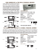
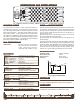
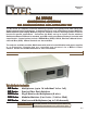
Fig. 1 VDM/32x32 Mainframe with RS232, IEEE488 and LAN Control, with BNC Signal Connections
INPUT and OUTPUT BUFFERSINPUT and OUTPUT BUFFERS
INPUT and OUTPUT BUFFERSINPUT and OUTPUT BUFFERS
INPUT and OUTPUT BUFFERS
Optional very wideband Buffers are available for all Input and Out-
put Channels. These buffers serve up to three different purposes:
1) They transform impedances to allow the solid state switch fab-
ric to be used for signals requiring other than two wire analog, for
example 50 ohm coax.
2) Input Buffers can be used to reduce signals to levels where
they can be safely switched by the matrix.
3) Output Buffers can have preset gains to boost signals to re-
quired voltages.
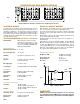
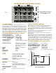
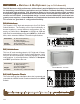
A typical Output buffer is shown schematically in Fig. 2. Resistors
Rs and Ri set the input impedance and also attenuate the input
signal (if needed), while Rout determines the output impedance.
The circuit is typically built with one of several standard small
signal Op Amps, but custom amplifiers are also possible. Speci-
fications for a typical small signal amplifier are shown below.
BUFFER SPECIFICABUFFER SPECIFICA
BUFFER SPECIFICABUFFER SPECIFICA
BUFFER SPECIFICA
TIONSTIONS
TIONSTIONS
TIONS
Bandpass (-3dB) Typically>500 MHz
Preset Gains (Av) 2 to 16
Output Current 80 mA typical
Rise Time 3100 V/us typical
The VDM Series is intended to switch small signal levels in a
nonblocking (any input to any output) and full fan out (any input to
any or all outputs) configuration. The heart of the system is a solid
state 32x32 switch fabric.
The basic system holds the neces-
sary control module, power supplies and the switch fabric
The system is completed by adding the required input or out-
put buffers. The buffers supply impedance matching and/or
signal level transformations. This design provides switching
for a large number of different signal types.
In 0-7 In 8-15
In 16-23 In 24-31
Out 0-7 Out 8-15
Out 16-23 Out 24-31
ACDEFGH
B
ACDEFGH
B ACDEFGH
B
ACDEFGH
B
I
O
A/C-In
IEEE-488
RS-232
LAN
WARRANTYWARRANTY
WARRANTYWARRANTY
WARRANTY
CYTEC Corp. warrants that all products are free from defects
in material or workmanship for a period of five years.
SOFTWARESOFTWARE
SOFTWARESOFTWARE
SOFTWARE
Free drivers and/or sample programs are available for the most
commonly available application programming languages.
Rout
Rf
Rg
Ri
IN
Rs
OUT
Fig. 2 Typical Output Buffer
VDM-2
ENVIRONMENTENVIRONMENT
ENVIRONMENTENVIRONMENT
ENVIRONMENT
ALAL
ALAL
AL
Dimensions
Weight
Operating Temperature
Storage Temperature
Altitude, Operational
Altitude, Storage
Humidity
19' rack mount x 5.25" H x 15.6" D
20 lbs. max. with buffers installed
0
o
to 65
o
C
-25
o
to 80
o
C
3,000 meters
15,000 meters
95% RH noncondensing to 30
o
C
POWERPOWER
POWERPOWER
POWER
90-264 Volts AC, 47-63 Hz
High Efficiency Switching
250 Watts Maximum for 32x32 Matrix
AC Input
DC Supply Type
Consumption
BANDPBANDP
BANDPBANDP
BANDP
ASSASS
ASSASS
ASS
Approx. 500 MHz (-3dB) for 0 dBm
0.5 dB at 0 - 300 MHz
1800 V/usec
Small Signal
Flatness
Slew Rate
CROSSTCROSST
CROSSTCROSST
CROSST
ALK / ISOLAALK / ISOLA
ALK / ISOLAALK / ISOLA
ALK / ISOLA
TIONTION
TIONTION
TION
-50 dB at 240 MHz
-60 dB at 240 MHz Non Adjacent
-40 dB at 360 MHz
-50 dB at 360 MHz Non Adjacent
Crosstalk
Isolation
MISCELLANEOUSMISCELLANEOUS
MISCELLANEOUSMISCELLANEOUS
MISCELLANEOUS
Switching Speed 100 ns plus any computer delay
Connections
VDM SPECIFICAVDM SPECIFICA
VDM SPECIFICAVDM SPECIFICA
VDM SPECIFICA
TIONSTIONS
TIONSTIONS
TIONS
BNC Signal Connections, AC inputand Re-
mote Control input are on rearpanel shown
in Fig.1. Optional signal connectors in-
cluding SMA, SMB, TwinBNC and Triax.