
Specifications
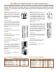
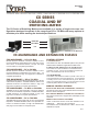

CXR-G SWITCH MODULES
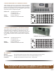
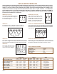
CXR/8x1-G
Is a bidirectional 8x1 conguration as shown in Fig. 7.
The module is normally closed to connector 0 when off.
These modules are designed with Type G coaxial relays arranged in a tree congurationas shown in Figs.
6 through 8 with on board logic that selects the appropriate relays to connect the selected input to the
common. Only one input can be switched to one output, and in the unenergized state or input #0 is con-
nected to the common, except the terminated modules which have an open condition. All -G Modules
are available with 50 or 75 ohm characteristic impedance. 50 Ohm modules are available with SMA or
BNC connectors. 75 Ohm modules have BNC's only. Combinations of these modules can be assembled
to form larger multiplexers or matrices.
CXR/4x1-G
This module is a bidirectional 4x1 conguration using connec-
tors 0 thru 3 of Fig. 7. It is available with the same connectors
and has the same bandpass and isolation as the 8x1 module.
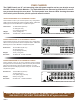
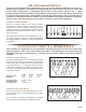
CXR/8x1-GT TERMINATED MODULE
This module switches any one of eight 50 or 75 ohm terminated
coaxial inputs to one output as shown in Fig. 10. Switching any
input removes the termination from that input and connects it
to the common.
CXR/4x1-GT TERMINATED MODULE
Switches any one of four coaxial inputs to common using inputs
0 thru 3 of Fig. 10. It is available with the same connectors and
has the same bandpass and isolation as the 8x1 module.
Fig. 10
Fig. 8
CXR/4x2-G
This module switches any two
of 4 coaxial ports to the two
commons as shown in Fig. 8.
CXR/2x1-G ( Form C )
This module switches the common to
one of two inputs as shown in Fig. 6. In
the unenergized position, the common
is connected to input A.
CXR/2x1-GT ( Form A )
Fig. 9
This module is a version of the
CXR/2x1-G module that has the
unused A/B connection terminated
into 50 or 75 ohm resistors as shown
in Fig 9. This module allows an off
state with both inputs terminated.
Fig. 6
Fig. 7
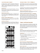
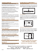
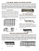
CXAR-6
RELAY SPECIFICATIONS
Switched Power
Carry Power
Termination rating
Operating Time
Life Expectancy*
Max Voltage
10 Watts ( 40 dBm)
20 Watts
5 Watts
3 ms
3x10
5
30 VDC
CXR/2x1-G-50-SMA or BNC 0.25 dB .5 dB 2.0 GHz -65 dB -55 dB -40 dB <1.25:1 @ 1 GHz
CXR/2x1-G-75-BNC 0.6 dB 2.0 dB 1.3 GHz -65 dB -50 dB NA <1.25:1 @ 750 MHz
CXR/2x1-GT-50-SMA or BNC 0.4 dB 1.4 dB 1.6 GHz -70 dB -60 dB -50 dB <1.3:1 @ 1 GHz
CXR/2x1-GT-75-BNC 0.8 dB 2.8 dB 1.1 GHz -70 dB -55 dB NA <1.3:1 @ 900 MHz
CXR/8x1-G-50 -SMA or BNC 0.5 dB .9 dB 2.3 dB -70 db -65 dB -50 dB <1.3:1 @ 1 GHz
CXR/8x1-G-75-BNC 1.2 dB 2.5 dB 1.2 GHz -65 dB -50 dB NA <1.3:1 @ 750 MHz
CXR/8x1-GT-50-SMA or BNC 0.7 dB 1.4 dB 1.5 GHz -70 db -65 dB -50 dB <1.3:1 @ 1 GHz
CXR/8x1-GT-75-BNC 1.3 dB 3.0 dB 1.0 GHz -65 dB -50 dB NA <1.3:1 @ 750 MHz
CXR/4x2-G-50-SMA 1.4 dB 2.4 dB 1.2 GHz -60 dB -50 dB NA <1.3:1 @ 650 MHz
CXR/4x2-G-75-BNC 1.5 dB 3.5 dB 800 MHz -60 dB -45 dB NA <1.3:1 @ 500 MHz
Insertion Loss Isolation VSWR
* @ 900 MHz 10 Watts
.5 GHZ 1 GHz -3 dB Point .5 GHZ 1 GHz 2 GHz