CYTEC SWITCHING SYSTEMS Quality Products Excellent Service Reasonable Prices FOR AUTOMATIC TEST, DATA ACQUISITION, COMMUNICATIONS AND CONTROLS AUTOMATED TEST AND DATA ACQUISITION COMPUTER CONTROLLED FROM ETHERNET LAN, IEEE488 (GPIB), RS232, USB or TTL COMMUNICATIONS MULTIPLEXERS MICROWAVE AND RF MATRIX LAN, WAN AND TELEPHONY DISCRETE RELAYS DIGITAL SERIAL DATA HIGH VOLTAGE OR CURRENT VXI, VME, PCI BUS SWITCH MODULES FIBER OPTICS FOR TECHNICAL ASSISTANCE ANALOG VIDEO AND RF OR SALES CONTACT 1-800-3
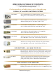
WEB CATALOG TABLE OF CONTENTS For application guidance you can try our web app: http://cytec-ate.com/appguide.php Click on products or links below to get to the right page. COAXIAL, RF and VIDEO SWITCHING SYSTEMS CXM SERIES DC to 40 GHz Microwave and RF Switching Systems. Multiplexers (1xN) and Matrices (NxM), Custom systems. CXAR SERIES DC to 1.2 GHz Coax and RF 1xN or 2xN Switching Systems. Mechanical Relay, 50 or 75 ohm. BNC, SMA, F, TNC.
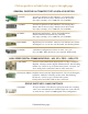
Click on products or links below to get to the right page. GENERAL PURPOSE AUTOMATED TEST & DATA ACQUISITION LX SERIES Versatile test platform w/ LED indicators. 128 switch points. Matrix, Mux or Discrete relays. Build to suit or off the shelf. Pico amps to 10 amps, uV to 1500 Volts, DC to 50 MHz. VX SERIES Versatile test platform w/ LED indicators. 256 switch points. Matrix, Mux or Discrete relays. Build to suit or off the shelf. Pico amps to 10 amps, uV to 1500 Volts, DC to 50 MHz.
Click on products or links below to get to the right page. FIBER OPTIC SWITCHING SYSTEMS FO SERIES Passive fiber optic switches. Single or Multi-mode. 1xN configurations. Any wave length. Build to suit or off the shelf. ST, LC, SC or other connectors. FX SERIES Fiber Optic Switch Matrix. Built according to specs. OEO Matrix regenerates and fixes signals. Call or e-mail for details. MESA CONTROL CHASSIS MESA 16 3.
BULLETIN CXM 7/2013 CXM SERIES MICROWAVE COAXIAL SWITCHING SYSTEMS The CXM Series Systems are computer controlled, passive bi-directional coaxial switching systems designed to handle 50 ohm RF signals from DC to 18 GHz, and in some cases up to 40 GHz. Two basic topologies are offered: Nx1 multiplexers and NxM nonblocking matrices. RS232 & IEEE488 controls are standard, while Ethernet, USB and front panel Manual Controls are optionally available.
CXM CHASSIS The CXM Series are 19" rack mounting chassis with built in power supplies and are designed to hold the CXM Microwave Switches selected by the user. The switches are typically mounted so that their RF connectors protrude through the rear panel. The front panels have discrete LEDs showing the status of all switch points. The front panels also hold the optional manual controls.
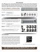
CXM/128 MAINFRAME OR -E EXPANSION CHASSIS These Chassis control up to sixteen 1x8 CXM switches arranged as shown on the drawing, or combinations of 1x2, 1x4 and 1x8 switches. LEDs visible through the front panel show switch and power Status. Add CXM switches, controls, and one CL8-VHP Display module for every eight switch points to complete the system.
CXM EXPANSION CHASSIS LED INDICATORS / STATUS FEEDBACK Cost Savings CXM/16 and CXM/32 LED Indicators LEDs are built into the front panel and are included in the chassis prices. All CXM Chassis can be built as either stand-alone mainframes or expansion Chassis. Multiple expansion chassis are controlled via a single MESA control chassis. This design allows configuration of large, complex systems with one point of control.
CXM COAXIAL MICROWAVE SWITCHES Standard CXM Switches are 50 ohm, bi-directional, failsafe, Normally Open switches with a bandpass of DC to 18 GHz. Microwave switches from 1x2 to 1x12 are available, and SMA connectors are standard. OPTIONAL FEATURES INCLUDE: Failsafe default to Port 0 closed, latching actuators, BNC, TNC or N Connectors, unused input ports terminated to 50 ohms and higher frequency or power handling capacity.
PROGRAMMABLE ATTENUATORS, SPLITTER/COMBINERS On a semi-custom basis RF devices such as Programmable Attenuators, Splitter/Combiners and Directional Couplers can be installed inside your CXM Chassis to furnish a complete, turn-key test setup. PROGRAMMABLE ATTENUATORS POWER DIVIDERS/COMBINERS Relay based and solid state attenuators are available in a variety of step sizes (such as 1 dB, 2 dB, 4 dB, 8 dB, etc.) and frequency ranges. Step size control is via Cytec's standard, simple programming commands.
BULLETIN BULLETIN CXAR 7/2013 CXAR & CT/8 CXAR SERIES COAXIAL SWITCHING SYSTEMS The CXAR Series are Computer Controlled Coaxial Switching Systems for 50 or 75 ohm RF Signals up to 1.6 GHz, or Low Leakage signals down to 100 Femto amps. These systems are typically used to configure 1xN multiplexers. Both Mainframes and Expansion Chassis are offered and hold a variety of different switch modules to form the desired configuration.
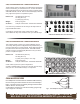
CXAR CHASSIS The CXAR Chassis are 19" rack mounting units with power supplies and are pre-wired to accept the CXR Series of Switch Modules. The Switch Modules are mounted so that their I/O connectors protrude through the rear panel. The front panels have discrete LEDs showing the status of all switch points and also provide optional manual controls. CXAR/16 MAINFRAME OR -E EXPANSION CHASSIS These Chassis control up to 16 switch points in any configuration.
CXAR/128 MAINFRAME OR -E EXPANSION CHASSIS These Chassis control up to 16 1x8 switch modules arranged as shown in the drawing or combinations of 1x2, 1x4 and 1x8 modules. LEDs on the front panel show Switch and Power Status. Add Switch Modules, a Control Module, and one CL8 Display module for each eight switch points to complete the system. 19" Rack Mount (483 mm) 15" deep (381 mm) 7" (4 RU) high (178 mm) 25 lbs (11.4 Kg) max 30 watts max.
CXAR EXPANSION CHASSIS LED INDICATORS / STATUS FEEDBACK All CXAR Chassis are available as Expansion Chassis for use with a MESA Control Chassis. This design allows configuration of large or complex systems with one point of control. Using a Mesa Controller and multiple Expansion Chassis has the following advantages: All CXAR Mainframe and Expansion Chassis have LED displays that show state of every relay.
CXR REED OR ARMATURE RELAY SWITCH MODULES These switch modules use reed or armature relays interconnected by characteristic impedance striplines and are completely bi-directional. They are an excellent , cost effective choice for applications below 200 MHz. BNC connectors are standard. Bus bars are available to build larger configurations, but lower bandpass. These modules provide the best solution for lower frequency applications that require coaxial connections.
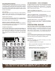
CXR-G SWITCH MODULES These modules are designed with Type G coaxial relays arranged in a tree configurationas shown in Figs. 6 through 8 with on board logic that selects the appropriate relays to connect the selected input to the common. Only one input can be switched to one output, and in the unenergized state or input #0 is connected to the common, except the terminated modules which have an open condition. All -G Modules are available with 50 or 75 ohm characteristic impedance.
CXR LOW LEAKAGE MODULE This module is designed with for applications where you need to measure extremely low currents or extremely high resistence. The module is arranged as two 4x1 sections that can be wired as an 8x1, 4x2 or many other configurations. A schematical representation of the module is shown in Fig. 11. Many jumpering options allow this module to be grounded or ungrounded or used with a driven guard circuit to improve speed and accuracy.
CONTROL MODULES OTHER HELPFUL COMPONENTS... IF-5C IEEE488/RS232 16 and 32 Channel Control This Module has both the IEEE488 (Talk/Listen) and the RS232 features detailed in Applications Bulletin AP-5. This combination module is used on all 16 or 32 channel chassis. CXBS COAXIAL BUS STRIPS IF-5 IEEE488/RS232 64 and 128 Channel Control This Module has both the IEEE488 (Talk/Listen) and the RS232 features detailed in Applications Bulletin AP-5.
BULLETIN CX/8 CX SERIES COAXIAL AND RF SWITCHING MATRIX The CX Series of Switching Matrices are available in a variety of single wire coax configurations designed to operate in the range from DC to 700 MHz with many options to minimize price while meeting the desired specifications.
CXB SERIES MODULAR SWITCH MATRIX The CXB Series of Modular Coaxial Switch Matrices provide incremental matrix sizes from 2x4 or 1x8 up to 32x4 or 16x8. 50 ohm signals from DC to 50 MHz can be switched, with isolation of -50 dB at 50 MHz. Up to 16 CXB Switch modules and CL8 Display modules are plugged into the coaxial motherboard to supply the required matrix configurations as shown in Figs. 1 and 2.
CXG SERIES DC to 700 MHz COAXIAL MATRIX CYTEC's CXG Series of coaxial tree switch matrices are available as 4x8 or 8x8 nonblocking configurations in 50 or 75 ohm characteristic impedance. The tree switch topology shown in Fig. 7, provides excellent attenuation and crosstalk specifications from DC to 700 MHz. The use of electro-mechanical relays make these systems completely bidirectional and capable of hot switching signals up to 24 watts.
CXL SERIES 8x8 BLOCKING MATRIX The CXL/8x8 blocking matrix is a compact and affordable, DC to 700 MHz coaxial 8x8, bidirectional matrix as shown in Fig. 9. The system will allow any input to be connected to any output but requires that the entire switch is reconfigured in order to establish a new path. This may cause a momentary disconnect in previously set paths when a new connection is desired.
BULLETIN VDX-2 2555 Baird Road, Penfield, New York 14526 (585) 381-4740 FAX (585) 381-0475 VDX SERIES VIDEO AND RF SWITCHING SYSTEMS CYTEC's VDX Series of Video and RF Switching Systems are based on a solid state switch fabric and are available in nonblocking, full fan-out configurations of 16x16 and 32x32, with bandpass to 200 MHz. Input and output buffers can be added to the basic switch fabric allowing a broad range of both 75 and 50 ohm impedance signals to be switched.
SPECIFICATIONS AND BUFFER OPTIONS RS-232 Fig. 2 LINK RS-232 UTP VDX/32x32 Mainframe with RS232 and LAN Control and BNC Signal Connections VDX SERIES MATRIX INPUT and OUTPUT BUFFERS The VDX Series is intended to switch small signal levels in a nonblocking (any input to any output), full fan out (any input to any or all outputs) configurations. The heart of the system is a solid state 32x32 switch fabric.
BULLETIN VDM(v1) 2555 Baird Road, Penfield, New York 14526 (585) 381-4740 FAX (585) 381-0475 VDM SERIES SOLID ST ATE VIDEO STA VIDEO,, RF or BALANCED LINE SWITCHING SYSTEMS CYTEC's VDM Series Switching Systems are based on a solid state switch fabric and are available in nonblocking, full fan-out configurations from 8x8 to 32x32, with a small signal bandpass to over 400 MHz.
SPECIFICA TIONS AND BUFFER OPTIONS SPECIFICATIONS A B C D E F G H IEEE-488 LAN In 24-31 H Out 8-15 G Out 0-7 F In 16-23 E In 8-15 D Out 24-31 C In 0-7 B Out 16-23 A A B C D E F G H A B C D E F G H A/C-In I O RS-232 Fig.
BULLETIN TX-1 2555 Baird Road, Penfield, New York 14526 (585) 381-4740 FAX (585) 381-0475 TX SERIES THREE STAGE MATRIX SWITCHING SYSTEMS CYTEC's TX Series Three Stage Matrix Switching System is completely nonblocking, full fan-out configurations from 16x16 to 128x128, with a bandpass to 140 MHz. The system can handle a wide variety of 50 and 75 ohm signals. Control options include RS232, IEEE488, LAN or LCD Keypad Manual Control.
SPECIFICATIONS AND BUFFER OPTIONS TX/128x128 Mainframe Rear View with IEEE488, RS232 and LAN Control Fig. 2 TX SERIES MATRIX INPUT and OUTPUT BUFFERS The TX Series is intended to switch small signal levels in a nonblocking (any input to any output), full fan out (any input to any or all outputs) configurations. For a 128x128 non blocking three stage matrix mainly consist of an input, center and output stage. Each Input stage is a 8x16 matrix. Sixteen input stages gives you 16x8 = 128 input connectors.
BULLETIN RJ(v4) 2555 Baird Road, Penfield, New York 14526 (585) 381-4740 FAX (585) 381-0475 RJ SERIES SWIT CHING SYSTEMS SWITCHING FOR COMMUNICA TIONS AND A UT OMA TED TEST COMMUNICATIONS AUT UTOMA OMATED The RJ Series of Computer Controlled Switching Systems are engineered for both analog and digital communication applications.
RJV SERIES - Matrices & Multiplexers (up to 144 channels) The RJV Series are high performance, bidirectional, passive Multiplexers or Matrices designed for demanding communication applications such as 100Base-T Network Switching. These units are built with high sensitivity Type A Armature Relays to insure low signal-to-signal crosstalk. Exceptional longitudinal balance and low insertion losses are achieved at high data rates. Connectors are CAT5 RJ45.
RJV Switch Modules Most RJV Switch Modules use high sensitivity, high isolation Type A Armature Relays and RJ45 connectors. Up to 8 poles are switched (but not on all models). Signals can be routed to the Common connectors on the individual modules or alternately to the motherboard bus. The bus interconnects the modules and creates larger multiplexers and matrices. The RJV / FOSM Fiber Optic Switch Modules are passive, bidirectional optical switches.
RJM SERIES - MODULAR MATRICES (4 or 8 wire / 16x8 or 32x4) The RJM Series are high Performance, bidirectional, passive Matrices and are designed to switch high speed communication signals, including T1, E1, DSL and 100Base-T Ethernet. High sensitivity Type A Armature Relays and RJ45 connectors are used to ensure high pair-to-pair isolation, and attenuation and crosstalk specifications are met.
RJE SERIES - MULTIPLEXERS (up to 16 individual 1x4) Each RJE chassis holds up to 16 of the RJE/ 4x1-8 Switch Modules as shown in the opposite figure. Each RJE/4x1-8 switches up to eight wires (as four pairs) on RJ45 connectors. These switch modules are designed for demanding high speed networking applications such as Gigabit Ethernet, ATM-155 and 100VGAnyLan. The chassis is offered only in configurations of one to 16 individual 1x4s.
Controls The RJ Series Mainframes are computer controlled via: IEEE488 BUS, RS232 Serial, Ethernet LAN, Universal Serial Bus (USB) or TTL Parallel Port. The Control Module selects any Mainframe switch point and is able to Latch, Unlatch and Request Status of the switch in both Matrix and Multiplex Modes. In the Matrix Mode, any number of switches can be closed at the same time. In the Multiplex Mode, only one switch can be closed at a time.
BULLETIN RS-4 2555 Baird Road, Penfield, New York 14526 (585) 381-4740 FAX (585) 381-0475 RS SERIES SWIT CHING SYSTEMS SWITCHING FOR A UT OMA TIC TEST AND COMMUNICA TIONS AUT UTOMA OMATIC COMMUNICATIONS The RS Series of computer controlled switching systems are designed to switch multiwire groups of signals of up to 25 wires.
RS MUL TIPLEXER MULTIPLEXER RSS MA TRIX MATRIX These are passive, relay-based multiplexers switching from 9 to 25 wire signals such as RS232, RS422 or TTL in applications including Modems, Printers or Token Ring. Their Bandpass is DC to 20 MHz. These are built up from the RSS/16x8 Solid State Modules, which in turn are plugged into pre-wired RSS chassis. Each module is an individual 16x8 Matrix, and multiple modules can be interconnected to form larger matrix configurations.
RSM MA TRICES MATRICES RSM Matrices are designed to switch multiwire data communications signals such as RS232, RS422 and Token Ring. RSM Systems can switch 9, 15 or 25 wires and are available with D9, D15 or D25 style connectors. SWIT CH MODULES SWITCH MAINFRAMES Mainframes are 19" rack mounted chassis, 7" (4U) high and 21" deep, with power supplies and pre-wired motherboards that hold Switch Modules, LED Display Modules and Control Modules.
CONTROLS The RS Series of computer controlled Mainframes are available with the following controls: combined IEEE488/RS232 (standard), or optional Parallel Port TTL, Ethernet LAN or USB. The controls select any switch and can Latch, Unlatch and request Status of the switch using either Matrix or Multiplex Modes. In the Matrix Mode, any number of switches can be Latched as required. In the Multiplex Mode, only one switch can be Latched at any time; any previously latched switches are cleared.
BULLETIN HXV (v5) HXV SERIES HIGH VOLTAGE SWITCHING SYSTEMS 25 The HXV Series are computer controlled switching systems designed for High Voltage applications. Standard systems handle signals up to 5000 volts, while custom systems switching up to 40 kV are possible. Typically applications include Hi-pot and high voltage IR testing. HXV/128 Mainframe with keypad manual control FEATURES: • • • • • • Standard relays hot switch up to 3500 volts or 3 amps, carry 5000 volts and 5 amps.
HXV CHASSIS The HXV Chassis are 19" rack mounting units with built-in power supplies that are pre-wired to hold the HXV Series switch modules. Switch modules are mounted so that their I/O connectors protrude through the rear panel. Every chassis front panel has discrete LEDs showing the status of all switch points and also holds the optional manual control. HXV/32 MAINFRAME OR -E EXPANSION CHASSIS This chassis controls 32 switch points. A number of different switching configurations are possible.
HXV/96 MAINFRAME This chassis controls up to 96 switch points. A typical application would be 12 HXV/8x1 Switch Modules, but many configurations are possible using different switch modules. One CL8 Display/Driver Modules is needed to drive each switch modules. The CL8s also have built-in LEDs that show switch status. Add switch modules, the required CL8s, a control module and the optional keypad manual control to complete the system. Standard chassis measure 15.6" deep and 7" high.
HXV SERIES SWITCH MODULES The HXV Series switch modules are built with special high voltage reed relays that hot switch up to 3500 volts and cold switch carry 5000 volts. Applications include HiPot testing, insulation breakdown testing and other extreme voltage requirements. Standard I/O signal connectors are either -SHV coaxial or -BP banana plugs. The modules can be wired together internally to furnish larger configurations while eliminating external connections.
BULLETIN LX-6 2555 Baird Road, Penfield, New York 14526 (585) 381-4740 Fax (585) 381-0475 LX SERIES GENERAL PURPOSE SWIT CHING MA TRICES SWITCHING MATRICES FOR A UT OMA TIC TEST ATION AND CONTROL AUT UTOMA OMATIC TEST,, INSTRUMENT INSTRUMENTA The LX Series are high reliability, low cost, versatile Switching Systems. A modular design concept is used. Interchangeable Control Modules, Switch Modules and Display Modules can be assembled into Matrices, Multiplexers or Individual Switch Point configurations.
LXA GENERAL PURPOSE SERIES The LXA Series are 19" rack mounting Mainframes or Expansion Chassis, 3.5" high, with motherboards that hold any of the LX Series of Switch Modules, Latching/Display Modules and a Control Module. LXA/128 MAINFRAME SWITCH MODULES LX8/G2 This chassis is 15.6" deep. It is built with power supplies and motherboards that hold a Control Module, up to 16 LX8 Switch Modules and 16 CL8 Latching/Display Modules. The Signal Motherboard busses the switch modules together (shown in Fig.
LXB MA TRIX SERIES MATRIX The LXB Series units are two pole switch matrices and are available as either Mainframes or Expansion Chassis. They are well suited for use in two wire data communications applications, including T1 and ISDN, where wiring is minimized and performance is optimized. The following matrix configurations are available: Two separate 16x4's in one chassis, one 16x8, one 32x4 or one 64x2. Signals connectors include BNCs, Screw Terminals or Three Pin Headers.
GX GROUP SWITCH LX CONTROL MODULES LX8/G2 Switch Modules can be used in either the GX/8 or GX/16 Group Switch Chassis to switch signals in groups of 16 wires in up to a 16x1 Multiplexer configuration. For more information see the GX Bulletin. The LX Mainframes can be computer controlled via the modules listed below. Each Control Module selects any Switchpoint and Latches, Unlatches and returns Status of that point.
BULLETIN VX-5 2555 Baird Road, Penfield, New York 14526 (585) 381-4740 Fax (585) 381-0475 VX SERIES SWITCHING SYSTEMS FOR AUTOMATIC TEST, INSTRUMENTATION AND COMMUNICATIONS The VX Series of low-cost, versatile Switching Systems use a modular concept of Switch Modules, Display Modules and Control Modules which can be assembled into VX/256 Mainframes as Matrices, Multiplexers or Individual Relays. All units have front panel LED displays and Status feedback of selected relays.
VX/256 CHASSIS The VX/256 Chassis consist of Mainframes and Expansion Chassis with pre-wired motherboards which accept 16 of the VX Switch Modules and Display Modules. The motherboards are assembled so that the Switch Module signal connectors are accessible from the chassis back panel and the LEDs are visible through the front panel. The VX/256 Mainframes have power supplies and are pre-wired for a Control Module.
VX GENERAL PURPOSE MODULES VX/G SWITCH MODULES VX/K SWITCH MODULES These modules have the inputs of 16 relays wired to header connectors on the rear edge of the module and the outputs wired to the motherboard as shown in Figs. 5 & 6. Plugged into the bussed motherboard, the modules can be wired in configurations of 16x16, 32x8, 64x4, 128x2 or 256x1. The following types of modules are available: VX16/G1 has 16 single pole relays wired to two 20 pin headers as shown in Fig.
GX GROUP SWITCH CONTROL MODULES VX16/G2 & VX16/G3 Switch Modules can be used in the GX/16 Group Switch Chassis to switch signals in groups of up to 48 wires in up to a 16x1 Multiplexer configuration. For more information see GX Bulletin. The VX Mainframes can be computer controlled via the modules listed below. Each Control Module selects any switchpoint and Latches, Unlatches and returns Status of that point.
BULLETIN J-8 2555 Baird Road, Penfield, New York 14526 (585) 381-4740 Fax (585) 381-0475 JX SERIES MATRIX/MULTIPLEXERS FOR DATA ACQUISITION AND AUTOMATIC TEST This compact and economically priced Series can be used as either Multiplexers, Matrices or Individual Switches. As Multiplexers, they can be used as a single multiplexer to switch a large number of inputs or outputs to one commpon port , or as a dual multiplexer to switch between either of two common ports.
SERIES JX16 SWITCH MODULES The JX16 Switch Modules plug into the JX/256 Mainframe and Expansion Chassis and typically are built with 16 relays and their associated solid state controls, including Status feedback. The Modules are available with high reliability reed relays that have a guaranteed life of 100 million operations and with the option of either Type S - Standard Dry Reed, Type M - Mercury Wetted Reed or Type LT - Low Thermal Reed.
JX16/AB SWITCH MODULES JX16/PROTO-I/O MODULE These Modules typically have 16 relays configured as an 8x2 Matrix so that any of 8 inputs can be switched to either of 2 outputs. Bandpass is better than 20 MHz (-3dB) and Isolation is less than 40 dB at 100 kHz when used in a JX/256 chassis. This module, shown in Fig. 10, plugs into the JX Series backplane and has logic to control 16 TTL Outputs or Relay Driver Outputs and 16 TTL compatible inputs.
CONTROL MODULES Plug in modules can control the JX/256 Mainframe from either TTL Port, Combined IEEE488 BUS / RS232 Serial BUS or 10Base-T Ethernet LAN. The Control Module selects any switch in the Mainframe and Latches or Unlatches the switch in either the Matrix or Multiplexer Mode and can also request the Status of selected switches. In the Matrix Mode, any number of relays can be selected and Latched or Unlatched. In the Multiplex Mode, only one relay is selected and Latched.
BULLETIN 4600-1 2555 Baird Road, Penfield, New York 14526 (585) 381-4740 FAX (585) 381-0475 4600 SERIES VERY HIGH DENSITY SWITCHING MATRICES CYTEC's new 4600 Series are economical, high density, passive, bidirectional switch matrices. Each chassis holds up to 2048 two pole Type A relays, and a modular design allows great flexibility in creating different switching topologies.
4600 SERIES MAINFRAME Fig. 1 4600 Mainframe Rear View STANDARD MATRIX CONFIGURATIONS 4600 SERIES SWITCH MODULES One of several different possible matrix configurations can be supplied by jumpering the 4600/8(8x2) Switch Modules and/ or the Chassis Motherboard as shown in Fig. 2. The matrix is passive and bidirectional, and any input can be routed to any output without interrupting previously connect I/O paths.
BULLETIN PX (v7) 2555 Baird Road, Penfield, New York 14526 (585) 381-4740 FAX (585) 381-0475 PX/512 SWIT CH MA TRIX SWITCH MATRIX The PX/512 Series of Switching Matrices are compact and economically priced units using high reliability Reed Relay Modules assembled into pre-wired Mainframes or Expansion Chassis to assemble a 32x16 Matrix, two 32x8 Matrices or a 64x8 Matrix with either single or two pole signal switching. Computer Control can be from IEEE488 BUS, RS232 Serial or 10Base-T LAN.
PX/32 SWIT CH MODULES SWITCH Each switch module has 32 single or two pole relays and includes the logic for Selecting the module, Selecting and Latching the relay and obtaining the Status of the relay. Status is obtained by checking the drive to the relays which verifies that the logic is operating correctly and that the selected relay is energized.
TWO POLE SWIT CH MODULES SWITCH These Modules are available as either 2x16 Matrices or two 2x8 Matrices and with either Type S dry reed relays, Type M mercury wetted reed relays or Type LT low thermal relays. The inputs to the modules can be either BNC receptacles (-N), 20 pin headers (-H) or screw terminals (-S). Both the center conductor and isolated shield of the BNC are switched.
SWIT CH SPECIFICA TIONS SWITCH SPECIFICATIONS Three types of switches are available, the Type S, Type M and Type LT. Type S Standard is a dry reed switch for most medium range applications. Type M Mercury is a mercury wetted switch for high power or low contact resistance applications. Type LT Low Thermal is a dry reed switch for low level applications with less than 1 microvolt offset.
Bulletin DXM-1 2555 Baird Road, Penfield, New York 14526 (585) 381-4740 FAX (585) 381-0475 DXM/64x64 and DXM/128x128 SERIES SOLID ST ATE HIGH SPEED DIFFERENTIAL D ATA STA DA SWIT CHING MA TRICES for ECL SWITCHING MATRICES ECL,, PECL PECL,, CML & More J2 J1 J1 J2 J2 J2 J2 J1 J1 J2 J1 J1 J2 Input 63-33 Odd J2 J1 J2 J2 Output 1-31 Odd J1 J1 Output 33-63 Odd J2 J1 16 output Buffers Input 62-32 Even J2 RS-232 J1 0 1 2 J2 O J1 J1 Output 32-62 Even I Input 30-0 Even J2 A/C-I
SPECIFICA TIONS AND BUFFER OPTIONS SPECIFICATIONS 80-94 96-110 112-126 80-94 64-78 64-78 The CML Input Module AC couples all inputs and provides pull up circuits to prevent unused inputs from floating and picking up crosstalk from live adjacent signals. CML Output Modules accept CML signals from the switch matrix crosspoint IC and pass them on to the output Densi-Shield connectors.
CONTROL & POWER SUPPL Y REDUND ANCY/HO T SW APP ABLILITY SUPPLY REDUNDANCY/HO ANCY/HOT SWAPP APPABLILITY MESA II CHASSIS w/ Redundant Controls DXM EXP ANSION CHASSIS EXPANSION The MESA II is a 19" rack mounting chassis, 5.25" high and 15" deep. It accepts one or two of the CM-8 IEEE488/RS232/Ethernet Control Modules and also has expansion ports that control up to 16 expansion chassis. All three remote interfaces can be in use at the same time.
DXM GENERAL SPECIFICA TIONS SPECIFICATIONS CONTROL OPTIONS Connections IF-8 IEEE488, RS232 & ETHERNET LAN Control Densi-Shield signal connections, AC input and remote control input. Optional signal connectors such as SMA, BNC and Triax are available on wired-out patch panels. RS232, IEEE488 and Ethernet all standard. Manual keypad optional. ENVIRONMENT AL ENVIRONMENTAL Dimensions/Weight 19' rack mount, less than 45 lbs - DXM/64x64 5.25" high x 15.6" deep - DXM/128x128 14" high x 15.
BULLETIN DX256-2 DX/256x256 SERIES SOLID STATE DIGITAL SWITCHING SYSTEMS CYTEC's DX/256x256 Series Switching Systems are based on a solid state switch fabric. The Standard DX system is designed to switch TTL, CMOS, LVTTL, IRIG, RS232 and RS422. Input and output buffers are used to convert to RS422 and/or RS232 signal levels. The DX is capable of switching data rates to 80 Mbps NRZ. The DX Matrix is a non blocking, full fan-out configurations from 64x64 up to 256x256.
SPECIFICATIONS AND BUFFER OPTIONS 0-63 I Output TTL to RS422 (D-78 Conns) OUTPUT O 64-127 Output 128-191 Output TTL to RS232 (3M Conns-68 pin) 192-255 A/C-IN Output Input RS-232 0-63 IEEE-488 Input 64-127 INPUT LINK RS422 to TTL (D-78 Conns) 128-191 UTP Input RS-232 192-255 RS232 to TTL Input DX/256x256 Mainframe Rear View with IEEE488, RS232 and LAN Control Shown with RS422 and RS232 Buffer Modules DX/256x256 SERIES MATRIX INPUT and OUTPUT BUFFERS The DX Series is intended to switc
OPTIONS Control Options Single Chassis Mesa Controller with Redundant Supplies and Controls UTP IEEE-488 RS-232 UTP 1 A Primary Redundant Control Control (w/ Keypad M.C.) B I I O O A/C - IN A/C - IN 1 RS-232 Mtx 0 RS-232 IEEE-488 LINK Allows for redundant supplies but not hot swappable. Allows for redundant controls on a single DX chassis. Allows for remote Power Supply monitoring. LINK • • • Redundant Control RS-232 Primary Control (w/ Keypad M.C.
Need a custom system? No problem! Here's a good example: Model 6260 DX/256x256 75 ohm TTL Matrix 12V 12V (+) (-) (+) (-) (+) (-) (+) (-) Output 0 to 15 16 to 31 Output 32 to 47 48 to 63 Output 64 to 79 80 to 95 0-31 32-63 64-95 OUTPUT 96-127 5V (+) Output 96 to 111 112 to 127 Output 128 to 143 144 to 159 128-159 Output 160 to 175 176 to 191 160-191 Output 192 to 207 208 to 223 192-223 Output 224 to 239 240 to 255 224-255 (+) (-) (-) RS-232 Input 0 to 15 16 t
BULLETIN GX-3 2555 Baird Road, Penfield, New York 14526 (585) 381-4740 FAX (585) 381-0475 GX SERIES GROUP SWIT CHING MA TRICES and MUL TIPLEXERS SWITCHING MATRICES MULTIPLEXERS Standard CYTEC Switch Modules are available that can switch 8, 16 or 32 signal wires simultaneously. These modules can be custom configured as Group Switches to handle large number of signals per switched crosspoint.
GX SERIES CHASSIS The GX Series Chassis are built as either single chassis Mainframes or as Expansion Chassis controlled by one GX Series Control Unit. For larger systems having more than 16 groups, the MESA Control Unit is used to control several GX/16 Control Units. GX MAINFRAMES GX CONTROL UNITS These single chassis Mainframes are built with their own dedicated power supplies, a Control Module, and have front panel status LEDs.
BULLETIN FO(v2) 2555 Baird Road, Penfield, New York 14526 (585) 381-4740 FAX (585) 381-0475 FO SERIES PASSIVE FIBER OPTIC SWIT CHING SYSTEMS SWITCHING CYTEC's FO Series Passive Fiberoptic Switches are computer controlled systems designed to switch standard fiberoptic wavelengths of 850 nm, 1310 nm and 1550 nm. Multimode 62.5/125 um switches are available for 850 and 1310 nm wavelengths, while singlemode 9/125 um switches handle 1310 and 1550 nm.
FO SERIES MUL TIPLEXERS MULTIPLEXERS Bidirectional Nx1 Multiplexers are assembled from standard FO Chassis by interconnecting Fiberoptic Switch Modules as shown schematically below. The interconnects are fiberoptic cables and are usually wired internally. The FO/16 Chassis can be configured as four 1x4s or two 1x8s, while the FO/32 is available as eight 1x4s or four 1x8s.
BULLETIN BULLETIN MESA-6 MESA(v7) 2555 Baird Road, Penfield, New York 14526 (585) 381-4740 FAX (585) 381-0475 MESA SERIES MA TRIX EXP ANSION SYSTEMS MATRIX EXPANSION The MESA Series Controllers make it possible to control several different CYTEC Expansion Chassis via a single control module. They are used to build large matrix or multiplexer configurations or simply run different types of expansion chassis.
MESA CONTROL UNITS There are three basic models of the MESA Control Unit: the MESA 16, the MESA 32 and the MESA II. Each contain power supplies and an expansion motherboard. The Control Module and Expansion Interface Modules plug into the motherboard so that one Control Module can control up to 32 Expansion Chassis. The system shown in Fig. 1 has a MESA 16 Control Unit and four Expansion Chassis arranged and addressed as a 32x16 Matrix.
CM-5 IEEE488/RS232 IF-6 LAN INTERF ACE INTERFA This Module installs with the MESA 16 & 32 and combines both IEEE488 Talk Listen and RS232 Serial Controls. The LAN Interface accepts TCP/IP packets from a 10BaseT Ethernet Network, converts the data into RS232 format, and then transmits it to the RS232 port located on the standard CM-5 Control Module installed in the MESA. Data is also transmitted in the reverse direction; that is, RS232 data from the MESA is converted and sent over the Ethernet LAN.
MESA II CYTEC MESA II Series Controllers allow the control of up to 16 separate expansion chassis from a single point of control. That is, the MESA II holds the overall system’s single Control Module, and it directly controls multiple expansion chassis. The MESA II can be used to build large Matrix or Multiplexer configurations requiring multiple expansion chassis, or it can simply run several different expansion chassis.
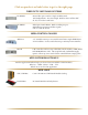
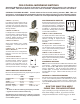
BULLETIN AP-5 INTERFACE BULLETIN AP-5 QUICK GUIDE - Call or E-mail for complete manuals. Mainframe Control Modules IF-5, IF-5C -- IEEE488 / RS232 Combination. IF-9 -- 100BaseT Ethernet LAN/RS232 Combination. IF-6 -- 10BaseT to RS232 converter used in conjunction with Mesa Control Modules (Large systems) CM-5 -- IEEE488 / RS232 Combination. CM-8 -- 100BaseT Ethernet LAN/RS232/GPIB Combination.
A guide to communicating with programmable switches CYTEC Switching Systems are available with a variety of communication interfaces. Which one is right for your application is dependent on what you are trying to accomplish. This bulletin lists the options and reasons for choosing them. Since switching systems are often used in conjunction with other, more complicated devices your choice may be dictated by those needs and all you need to know is that we support that option.
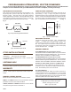
GPIB? TTL? RS232? Ethernet? USB? Which should I choose? We always feel the best choice is to use what you know. If you are set-up for GPIB and already are familiar with the interface it's the logical choice. If you're starting from scratch and haven't written software yet you should base the decision on the requirements. The guide below provides answers to commonly asked questions: Requirement Speed Usually a requirement of automated test apps. GPIB, TTL or possibly Ethernet.