
Specifications


INSTRUCTION AND MAINTENANCE MANUAL
The drawings and the technical data are R.M. S.p.a. - © R.M. S.p.a. - Revision 01.01.200716/44
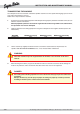
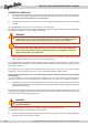
DANGER
If the stop dog is not disengaged when the carriage is jacked up, the machine can be
severely damaged.
CAUTION
It is essential when jacking up the carriage to disengage the stop dog that meshes with
the reel drive gear (pos. 2, photo D).
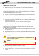
INSTALLATION INSTRUCTIONS
1. Before placing the machine on the ground, install the wheels and the drawbar fixing them with the
appropriate bolts (pos.2 photo A).
The rear support legs (pos. 3, photo A) must also be inserted in their housings as shown in the figure.
The legs cannot be inserted if the machine has been lowered to the ground.
Once the machine has been towed by the tractor for about 1 km, the tightening performance of the following
parts should be checked: wheel retaining nuts, axle fixing bolts.
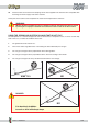
2. Install the rain gun skid as shown in the photograph. Beforehand, use a file to remove any burrs left by
the galvanising process. Put the legs (pos.1 photo C) in their house 7 photo C.
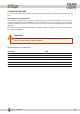
The wheel track (measured between wheel centres) must not be less than 1.4 m. If the carriage is used with a
lesser track the stability of the machine could be prejudiced.
3. Pull out about 2 m of hose (pos. 2 photo C). Refer to the section on “USING THE MACHINE” for comple-
te instructions on how to do this.
Couple the flange (pos. 3 photo C) to the carriage, after having inserted the rubber seal.
4. Install the machine’s rain run fixing it to its skid (pos. 5 photo A).
The tapped fitting on the skid carriage must be covered with Teflon or other sealing material before
screwing down the rain gun.
Tightening performance on the rain gun must be extremely firm to prevent it from working loose during
operation. Tighten it using a socket wrench.
5. Make a preliminary regulation of the rain gun’s sector (using pos.4 photo B) and install a nozzle sized for
the water supply volume.
6. Bring the sprinkler skid carriage to the disengage bar using the crank handle in the machine’s equipment
kit (pos. 1, photo D). Check that the stop bar (pos.2 photo E) passes under pos.3 photo E.
At this point, raise the carriage using the mechanical jack (pos.1 photo E).
7. Check if the swivel plate locking pin is in its seating (pos. 1, photo F).
8. Check if the stop dog (pos. 1, photo D) is inserted into the reel drive gear.
9. Check the inflation pressure on the machine’s tyres. If necessary fill them to the correct pressure of 3 bar
= 45 Psi.