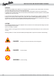
INSTRUCTION AND MAINTENANCE MANUAL TABLE OF CONTENTS SECTION INTRODUCTION CHAPTER 1 INTRODUCTION Notices .................................................................................................................................................................... page Legend .................................................................................................................................................................... page Who to contact for a problem ...........................
SECTION OPERATOR CHAPTER 4 USING THE MACHINE Operating conditions ............................................................................................................................................... page Unwinding the hose ................................................................................................................................................. page Machine drive and speed adjustment ..........................................................................................
INSTRUCTION AND MAINTENANCE MANUAL 4/44 The drawings and the technical data are R.M. S.p.a. - © R.M. S.p.a. - Revision 01.01.
INTRODUCTION PART I Section 1: Introduction 5/44
INSTRUCTION AND MAINTENANCE MANUAL NOTICES This Operating and Maintenance Manual is an integral part of the sprinkler system and must follow the machine whenever sold to another owner or transferred among farms. The manual should be kept carefully, read and placed readily at the disposal of all persons involved with it. In particular, this manual must be read carefully and fully understood by the machine operators and the people responsible for safety on the farm.
WHO TO CONTACT FOR A PROBLEM When the need arises, the customer can contact our Technical Assistance Service by calling the following numbers: In ITALY from abroad 0521 872321 ++39 0521 872321 This service offers the customers the solutions to the various problems that can crop up or will provide an on-site visit by a specialist Service Engineer. Many technical problems can be solved by very minor service work.
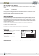
INSTRUCTION AND MAINTENANCE MANUAL TECHNICAL SPECIFICATIONS - ENVIRONMENTAL SPECIFICATIONS - Operating temperature range min. +10°C max. +40°C. - NOISE LEVEL Due to its very nature, the machine is not noisy. - SAFETIES The machine is complying with European Union Directives: EEC 89/392 dated 16/6/89; EEC 91/368 dated 20/6/91; EEC 93/44 dated 14/6/93; EEC 93/68 dated 22/7/93 (machine directive); EEC 89/391 (work site safety and hygiene).
GENERAL SAFETY CONDITIONS When the machine is put on work for the first time and at start up each day, the automatic cycle, the normal work cycle and, in fact, whenever the machine is used, the following general safety conditions must be applied: - Before starting the machine, read this manual completely and carefully and apply all the safety prescriptions it details.
INSTRUCTION AND MAINTENANCE MANUAL PROHIBITIONS The following prohibitions must be observed when operating the machine: • • • • • • • • • • • • • • • • • • • • • • • • • Do not tamper with or cut out safety devices. Do not inspect the machine while it is running. Do not sit on the protective casings. Do not lean on the machine when it is running. Do not sit on the components making up the machine. Do not use the machine or parts of it for uses other than those detailed in this manual.
HANDLING PART II Section 2: Handling 11/44
INSTRUCTION AND MAINTENANCE MANUAL TRANSPORTING THE MACHINE Use adequate steel wires to load or unload the sprinkler machine. Use the specific hoisting lugs (one or two on each side of the machine's chassis). Follow these steps to hoist the machine: 1. A portal crane or other lifting equipment with adequate lifting capacity should be available so that you can hoist the machine from above.
STORING THE MACHINE If the machine is not installed immediately and needs to be stored temporarily, it must be stored in a dry covered place. DISPOSING OF THE COMPONENTS The estimated working life of the machine is 25,000 work hours under normal conditions. At the end of the machine's working life, the owner must dispose of it in full compliance with current regulations. First, all lubricants should be emptied out and all the parts cleaned.
INSTRUCTION AND MAINTENANCE MANUAL 14/44 The drawings and the technical data are R.M. S.p.a. - © R.M. S.p.a. - Revision 01.01.
INSTALLATION PART III Section 3: Installation 15/44
INSTRUCTION AND MAINTENANCE MANUAL INSTALLATION INSTRUCTIONS 1. Before placing the machine on the ground, install the wheels and the drawbar fixing them with the appropriate bolts (pos.2 photo A). The rear support legs (pos. 3, photo A) must also be inserted in their housings as shown in the figure. The legs cannot be inserted if the machine has been lowered to the ground.
10. Check to make sure that one of the couplings on the hose supplied in the machine’s kit is compatible with the fittings on the line supply water to the machine. At this point, the machine can be coupled to the tractor and transported to its work site. WARNING RM Spa declines all liability for injury to people or animals or damage to property caused by oversight or improper installation and connection work carried out on the machine.
INSTRUCTION AND MAINTENANCE MANUAL 18/44 The drawings and the technical data are R.M. S.p.a. - © R.M. S.p.a. - Revision 01.01.
USING THE MACHINE PART IV Section 4: Using the machine 19/44
INSTRUCTION AND MAINTENANCE MANUAL OPERATING CONDITIONS 1. The machine must be towed by a tractor whose weight is greater than or at least equal to the weight of the machine plus the weight of the water inside the hose. For more details on this refer to the section on “TRANSPORTING AND HANDLING THE SPRINKLER”. 2. The Highway Code current in the country of use must be followed whenever the machine is transported on road. Note that RM sprinkler machines are not certified for on-road operation.
CAUTION The lowering of drawbar support foot has to be carried out by only one person who will have to make sure that no obstacles lie under the bar axle. RM Spa declines all liability for damages occured incase the above prohibition has not been respected. B. Remove the pin on the rotation (pos. 1 photo F) and then rotate the hose wheel by pushing on the back side of the rain gun carriage.
INSTRUCTION AND MAINTENANCE MANUAL The support legs must not be cranked down with the handle more than 15 cm. If this has to be done, first change the hole in the bracket. Regulate carriage track with the fixing bolts (pos. 7, photo C) for the wheel width required (the track must never be less than 1,4 m). To ensure good rain gun skid carriage return, the hose must always be centred between the two wheels. Lower the carriage with the wheel on the hydraulic pump (pos. 1, photo E).
6. When the hose has been unreeled, before going back to the machine, make sure that the rain gun carriage is correctly positioned (using sectors pos.3 photo B). 7. Reinsert the stop dog turning clockwise (pos. 2, photo D) and make sure that the turns of hose still on the reel are nicely close together (pos. 1 photo L). If they are not, bring them together and tension them using the crank on the PTO (pos. 1, photo D). DANGER Do not use this crank when the hose is being reeled in.
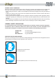
INSTRUCTION AND MAINTENANCE MANUAL To give you a clearer vision of what is meant by “safety distance”, the illustration below summarises the distances to be observed during the various stages. B A C Three operational areas are shown: A= The rain gun carriage: this is where irrigation actually takes place. The minimum distances are 5 m at the sides and 3 m from the back. B= Hose: the water transfer area is not dangerous but it is best to maintain a safety distance of 2 m.
MACHINE DRIVE AND SPEED ADJUSTMENT Engage the drive lever (Pos. 7, photo H) by pulling it towards left and use the by-pass to engage the desired drive speed (pos. 3, photo H). To adjust the speed: slacken off knob (pos. 2 photo H), engage the manual by-pass valve (pos. 3, photo H). Set the speed as required and then re-tighten knob (pos. 2, photo H) to lock the machine at that speed.
INSTRUCTION AND MAINTENANCE MANUAL FAST HOSE EMPTYING AND REWIND To empty the hose, it should be unwound for not more than 50% of its length following the instructions given in the section on “UNREELING THE HOSE”. Reel the hose back with the PTO (pos. 8 photo H) with the gear unit lever in the disengage position (lever pos. 7 photo 7 towards right) and remove the drain plug on the carriage. If the drain plug is not installed, remove the rain gun.
OPERATING INSTRUCTIONS FOR THE VDO DIGITAL TACHOMETER The VDO digital speedometer installed on the machine has been factory programmed. This instrument can read instantaneously the hose rewinding rate and show this on the display as meters per hour. The display also gives the first decimal for the speed and the current time. Speed range is from 5 to 140 m/h. This instruments works with a 3V battery (Type CR 2032/Sony) with a working life of around 2 years.
INSTRUCTION AND MAINTENANCE MANUAL VDO C05 CYTEC INSTRUMENTS: 1) Press some times the key to display ODO and then press the key for at least 3 seconds. 2) Now m/h and km/h are gleaming alternatively; when km/h is displayed, press the key to fix it. 3) The instrument is now automatically proposing the programm number (4 digits). The first digit on right starts gliding; when the correct number is displayed, press the key to confirm it. Do the same procedure for all other digits.
1 2 3 4 5 Section 4: Using the machine 29/44
INSTRUCTION AND MAINTENANCE MANUAL CALIBRATION OF VDO INSTRUMENTS: Machine 540 Inside diameter of drum Calibration with 3 magnets Calibration with 1 magnet 750 2367 1183 (with pulley) 30/44 550 870 2126 560 870 2090 1568 570 1040 2232 1674 580 1240 2730 581 1240 2730 581 chain 1240 590 1420 2773 600 1420 2690 600 1320 1553 690 chain 1320 1379 690 chain 1340 1390 690 chain 1420 1415 700 1524 2397 700 1340 2265 790 1340 800 1700 2591 1541 800 1500
MAINTENANCE PART V Section 5: Maintenance 31/44
INSTRUCTION AND MAINTENANCE MANUAL GENERAL MAINTENANCE REGULATIONS All maintenance and repair work must be done by expert and specialist personnel. All service engineers must work in full compliance with industrial accident prevention regulations. They must wear suitable protective clothing. In this context, refer to the section on “GENERAL SAFETY NOTICES”, part of the “INTRODUCTION” to this manual.
SERVICING PART VI Section 7: Servicing 33/44
INSTRUCTION AND MAINTENANCE MANUAL SERVICING INSTRUCTIONS During the machine’s normal working life, the machine can stop or lose its correct regulated settings. In these situations, follow these steps: ° Refer the matter to an expert service engineer. Only a service engineer can deal with these kinds of problems. ° The service engineer should identify the type of problem from a reading of the pages below on Troubleshooting the machine.
If the turbine does not turn or does so very slowly: Install a nozzle 2-4 mm larger on the rain gun (pos. 4, photo A). Try again and check the rain gun throw. If necessary try another nozzle to get a better throw (if the nozzle is too big or too small for the water volume, the throw will be shortened. Check on the in-feed gauge (pos. 1 photo H) if the pressure still exceeds 4 bar. If it is less, increase the pressure to reach the optimum level.
INSTRUCTION AND MAINTENANCE MANUAL PROBLEM REMEDY The machine moves or slides on the ground when reeling in the hose Attach the rear support legs better. If this does not work, act immediately with the following procedure: Put the gear lever in 4th (refer to the section “REGULATING REELING IN SPEED”; disengage the stop dog (pos. 2, photo H); open the by-pass valve to slow down or stop the turbine. Do not touch lever (pos. 7, photo H).
PROBLEM REMEDY Re-reeling speed is not constant It should be noted that the speedometer installed gives an approximate hose re-reeling rate reading with a an error of ± 15%. The instrument is calibrated on half the entire length of the hose. To solve this problem, use a lower gear unit speed (2nd rather than 3rd) with the same reeling in rate. Then increase the speed of the turbine and use a chronometer to check the actually running speed.
INSTRUCTION AND MAINTENANCE MANUAL 38/44 The drawings and the technical data are R.M. S.p.a. - © R.M. S.p.a. - Revision 01.01.
SPARE PARTS PART VII Section 7: Spare parts 39/44
INSTRUCTION AND MAINTENANCE MANUAL SPARE PARTS When order spare parts, always specify the following information: 40/44 1. The year the machine was fabricated. 2. The machine’s Serial N° 3. Diameter and length of the hose installed. 4. Order code Number for the part or an exact description of the part. 5. Short description of the presumed cause of the breakage or the wear. 6. Type of shipping required (parcel post, sea or air freight). The drawings and the technical data are R.M. S.p.a. - © R.
Section 7: Spare parts 41/44
INSTRUCTION AND MAINTENANCE MANUAL NOTE 42/44 The drawings and the technical data are R.M. S.p.a. - © R.M. S.p.a. - Revision 01.01.
/44
INSTRUCTION AND MAINTENANCE MANUAL 44/44 The drawings and the technical data are R.M. S.p.a. - © R.M. S.p.a. - Revision 01.01.