
Specifications

C2-6104A OPERATION MANUAL
37
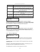
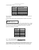
In Normal mode, the borders are set as follows:
Tally input pin
pulled low
Activation result on
a 4-window system
TI1 Window A has a red border
TI2 Window A has a green border
TI3 Window B has a red border
TI4 Window B has a green border
TI5 Window C has a red border
TI6 Window C has a green border
TI7 Window D has a red border
TI8 Window D has a green border
Please note that you may need to reduce the window size in order to see the full
colored border.
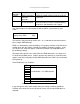
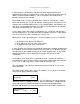
In Presets mode, the preset to be activated (loaded) is defined in the next menu
item.
This allows each of the 8 Tally input pins to be assigned a different Preset. Simply
adjust the first number to match the Tally input pin that needs to be assigned and
then select the Preset number to be loaded when that input pin is pulled low.
By default, the following are assigned:
Tally input pin
pulled low
Preset loaded
TI1 1
TI2 2
TI3 3
TI4 4
TI5 5
TI6 6
TI7 7
TI8 8
8.10 Items associated with the Adjust ethernet group
(Please note that not all units have this sub-menu.)
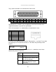
Your unit can be remotely controlled via its RS-232 serial port, but some units can
also be controlled via a Local Area Network using the Ethernet connector. This
provides TCP/IP communications to and from the unit using a custom protocol.
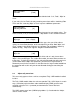
Adjust tally
Input [1] = Preset [1]