
Specifications

C2-6104A OPERATION MANUAL
36
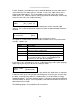
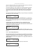
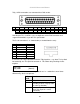
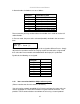
Tally / GPIO connections are connected via a D25 socket:
13 12 11 10 9 8 7 6 5 4 3 2 1
5v TX+ RX+ GND TI8 TI7 TI6 TI5 TI4 TI3 TI2 TI1 GND
TX- RX- GND TO8 TO7 TO6 TO5 TO4 TO3 TO2 TO1 GND
25 24 23 22 21 20 19 18 17 16 15 14
Note that the TX+/- and RX+/- pins are duplicates of the RJ45 connector and
support RS-422/485, as per the TSL specification.
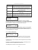
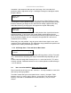
The RJ-45 connection is as shown below (as viewed from the rear):
Pin Function Direction
1 0v GND
2 0v GND
3 TX- OUT
4 RX+ IN
5 RX- IN
6 TX+ OUT
7 No connection
In all cases, the Tally output bits match the Tally input bits – e.g. when TI3 is pulled
low externally, the TO3 pulls low to match it. This allows daisy-chaining of units
together.
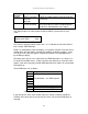
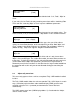
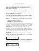
This sets up the mode that the Tally module runs in – and defines one of three
different ways that it can operate:
Tally
mode
Result
Disabled Tally I/O is disabled.
Normal Sets border colour of the window
according to which Tally input bits
are active (pulled low).
Presets Activates a preset according to
which Tally input bit is active
(pulled low).
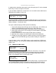
Adjust tally
Tally mode [Normal]