
Installation & Assembly

Page 3 of 4
ASSEMBLY INSTRUCTIONS (continued)
24W Power Adaptor
Outlet
On / Off Switch
Connecting fixture to fixture
1
4
2
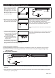
2. Secure the mounting clips (BB)
to the mounting surface with the
dry wall screws (AA) provided.
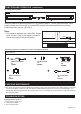
The cabinet lighting fixture units can be connected by using plastic connector or by using linking cord (12 inches).
Note: Maximum number of cabinet light fixtures per run should not exceed power supply wattage rating.
(Maximum 24W)
3
1. Place the mounting clips (BB)
apart and mark with a pencil.
Marks should be: 9 in. apart
for models X0115 ;16 in. apart
for models X0114
Mounting clips (BB) should be in
line with each other.
AA
BB
BB
a
b
BB
Fig.6.
Outlet
24W Power Adaptor
1. Align plastic connector (CC) on one end of new fixture (A) with plastic connector (CC) on one end of existing
fixture (A).
2. Push new fixture (A) to existing fixture /(A) until fixtures (A)are flush and connectors snap together by using plastic
connector (CC). (See Figure. 6)
A. Using plastic connector:
CC
3. Install the cabinet light fixture (A)
into the mounting clips (BB):
a. Latch one side of the cabinet
light fixture (A) into the two
mounting clips (BB).
b. Latch the other side of the
cabinet light fixture (A) until
fully secured.
The cabinet light fixture (A) may
be detached by using a small
flathead screwdriver (not included) between hooks and
prying outward on the cabinet light fixture (A).
4.Plug the link connector into either of the two cabinet
light connectors and plug the 24W power adaptor
into a 120VAC 60HZ outlet. (See Figure 4)
Note: The 24W power adaptor has a molded plug on
one end and a link connector at the other end.
5.Turn on the power at the main fuse or circuit breaker
box.
6.Press the on/off switch to turn on the fixture, when you
press the on/off switch again, the fixture will turn off.
(See Figure 4)
A
A
B
A
B