
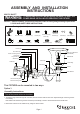
Installation Guide


2. Thread long screws through
the cross bar, then secure them with two
lock nuts. Adjust the length of the long
screws if necessary.
Note: Make sure that the long screws
are lined up horizontally, in order to
ensure that the fixture will be level.
3. Loosen and discard the green grounding
screw from the cross bar.
4. Place the cross bar to a proper position.
a) If the wall material is wood:
Attach the cross bar to the wall,
then secure the dry wall screws
through the set holes to the wall.
b) If the wall material is cement:
Mark the holes where you want to
place the cross bar on the wall.
Drill the holes and insert the anchors
into the holes, then attach the
cross bar to the wall, secure the
dry wall screws into the anchors.
5. Connect the pipes in turn as shown in
Fig.1. Thread plug cord through the
assembled pipes, swivel, threaded pipe,
the bottom hole of the back plate, washer,
and hex nut.
6. Secure the assembled pipes to the back
plate by using the washer and hex nut.
7. Thread the plug cord through two holes
of the strain relief. Pull the plug cord
down until the strain relief touches the
back plate.
Note: Adjust the strain relief can decrease
or increase the length of the exposed plug
cord.
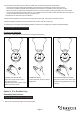
8. Cut any excess plug cord leaving 10
inches from the back plate. Slit the plug
cord apart in 5 inches. Peel off insulation
of the two wires in 5/8 inch. (See Fig.2)
9. Pull out the source wires from the back
plate. Make wire connections using wire
nuts as follows:
---The black wire from the back plate to
the smooth wire (marked) from the
plug cord.
---The white wire from the back plate to
the ridged wire (unmarked) from the
plug cord.
Carefully put the wires back into the
back plate.
10. Attach the back plate to the cross bar by inserting the long screws, then secure it with the ball nuts.
141205
Page 3
Stopper
Plug Cord
Strain Relief (H)
Fig.1
Plug Cord
Back Plate
5/8"
5"
10"
Pipe
Pipe Strap (N)
Dry Wall Screw (O)
Plug
Back Plate
Wire Nut (F)
Glass bracket
Socket Ring
Bulb Type A Max.60W
(not included)
Socket
Glass Shade
Long Screw(C)
Cross Bar (A)
Dry Wall Screw(O)
Lock Nut
(D)
Ball Nut (G)
Anchor (L)
Swivel (I)
Hex Nut (J)
Washer (K)
Set Screw
Threaded Pipe (M)
Anchor (L)
Fig.2
Cover
Bushing