
Installation Sheet
ASSEMBLY AND INSTALLATION
INSTRUCTIONS
TO AVOID RISK OF ELECTRICAL SHOCK, BE SURE TO SHUT OFF
POWER BEFORE INSTALLING OR SERVICING THIS FIXTURE.
161120
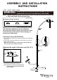
Metal Pad (B) Allen (C)
Lock Nut (A)
NOTE: 1. Before installing, consult local electrical codes for wiring and grounding requirements.
2. READ AND SAVE THESE INSTRUCTIONS.
L0001 / L0002 / L0003 / L0004
WARNING:
TO AVOID RISK OF ELECTRICAL SHOCK, BE SURE TO SHUT OFF
POWER WHILE INSTALLING OR SERVICING THIS FIXTURE.
Hardware Package (inculded):
Turn off the power at fuse or circuit
Installation Steps (K0022/K0023)
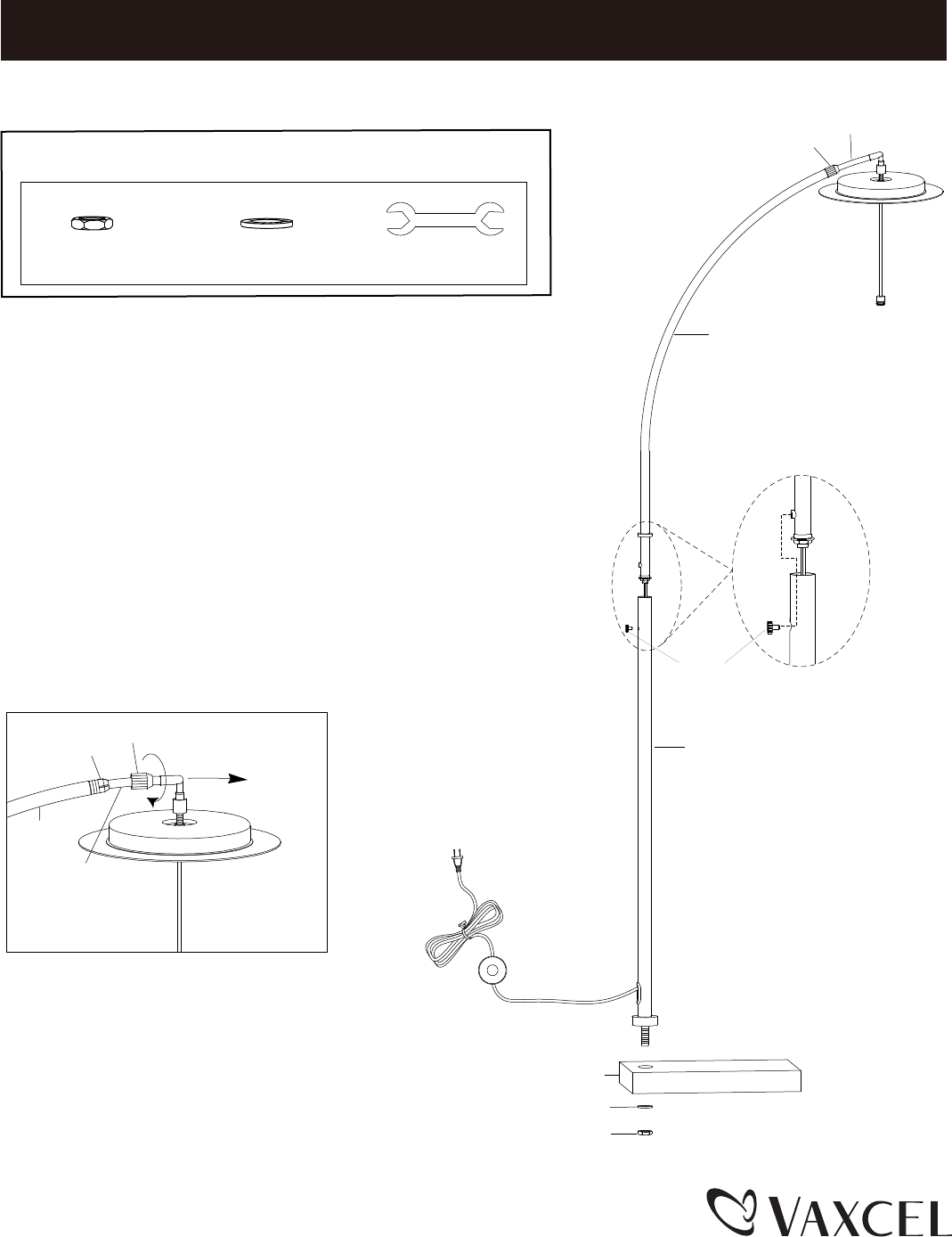
1. Attach the column into the hole of base and tighten it with metal pad
and lock nut.
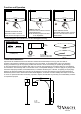
2. Pull the fixture wires and insert the arm into the hole of column and
tighten it with set screw.
Make sure the screw hole of column aligns with threaded hole
of arm and arm in the middle of the base.
Warning: LED electronics can be damaged by electro
static discharge (ESD)shock. Before installation,
discharge yourself by touching a grounded bare metal
surface to remove this hazard. To avoid damage, do
not touch the LED module.
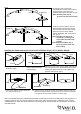
3. Unscrew the lock screw from the arm to slide
the inner arm out from the arm. (Fig.1)
Note: Hold the inner arm up for suceeding in
unscrewing lock screw and to prevent
it from scuffing.
Set Screw
Arm
Inner Arm
Screw
Column
Lock Nut (A)
Metal Pad (B)
Base
Adjusting the length of the inner arm (Fig.1,2,3)
Arm
Plastic Clip
Inner Arm
Lock Screw
Fig.1