
Installation Sheet


PAGE: 2 / 4
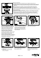
Fig.6.
Fig.7.
Screw &
Lock Washer
Decorative Housing
Lamp Plate
Lamp Plate
Switch Box
Wire Nut
Mounting Strip
Make wire connections using wire nuts:
1.) The motor white wire to the light
white wire.
2.) The motor blue wire to the light
black (or blue) wire.
Attach the lamp plate to the switch
box by aligning holes, then secure it
with lamp plate screws.
070614
TM
After making the wire connections, the wires should be spread apart with the
grounded conductor and the equipment-grounding conductor on one side of the
outlet box and the ungrounded conductor on the other side of the outlet box.
After the splices have been made, they should be turned upward and pushed carefully
up into the outlet box.
Instructions for supply connections: Conductor of a fan identified as grounded
conductor to be connected to a grounded conductor of power supply.Conductor of
a fan identified as ungrounded conductor to be connected to an ungrounded
conductor of power supply, conductor of fan identified for equipment grounding to
be connected to an equipment-grounding conductor.
Make wire connections:
1). The white motor wire to the white wire from outlet box with a wire nut.
2). The black and blue motor wires to the black wire from outlet box with a wire nut.
3). The ground wire from ceiling outlet box to the ground wire from the motor with
a wire nut.
Attach the holder cap and the blade
holder to the fan blade by aligning
holes (the fan blade should be placed
in between blade holder and blade
holder cap). Then secure them with
three blade screws. Repeat with the
others fan blades.
Secure blade holders to the motor with
motor screws and washers.
Fig.9.
Motor Screw
& washer
Blade Holder
Switch Box
Fig.10.
Lamp Plate Screw
Fig.11.
Fig.12.
Install bulbs (not included). See
relamping label at socket area or
packaging for maximum allowed
wattage.
Socket
Bulb (not included)
The decorative housing has two mating
slots and two mating holes. Position both
slots on the decorative housing directly
under and in line with two screws and
washers in the mounting strip. Lift the
decorative housing, allowing the two
screws and washers to slide into the
mating slots. Rotate the decorative
housing counterclockwise until both screws
from the mounting strip drop into the slot
recesses. Tighten screws securely.
Install two screws and washers, removed
in fig.2, into the mating holes of the mounting
strip and tighten to secure the decorative
housing to the mounting strip.
Holder Cap
Blade Screw
Fig.8.
Blade Holder
Fan Blade