
Installation Sheet
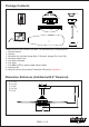
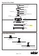
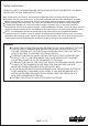
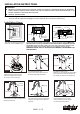
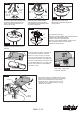
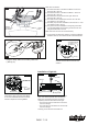

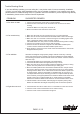
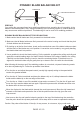

Fig.16
Hanger
Bracket
Hanger
Ball
Receiver
1.
4.
5.
6.
2.3.
Antenna:
DO NOT CUT
OR SPLICE
Make wire connections:
1) The Motor white wire to the white "To Motor N" wire from
Receiver with a wire nut.
2) The Motor black wire to the black "To Motor L" wire from
Receiver with a wire nut.
3) The Motor blue wire to the blue "For Light" wire from
Receiver with a wire nut.
4) The white wire from Outlet Box to the red "AC in N" wire
from Receiver with a wire nut.
5) The black (hot) wire from Outlet Box to the red "AC in L" wire
from Receiver with a wire nut.
6) The ground wire from Outlet Box to the green ground wire
from the Hanger Ball and the green ground wire from the
Hanger Bracket with a wire nut.
Make sure all of wire nuts are connected firmly.
*** Tuck all wire nuts and wires carefully up into the Outlet Box,
EXCEPT antenna, which should remain outside Outlet Box.
Attach the canopy to the hanger bracket,
and then secure it with four screws and
washers.
Insert the Blade through the slot on the
Center Band. Align holes and fasten Blade
to the motor with Blade Screws and rubber
washers. Repeat for remaining Blades.
Unscrew the bolt nuts and remove the decorative
clips, cover and lamp shade from the LED pan.
Make wire connections using the connectors
respectivly from the switch box and fan light.
--- The blue wire from the switch box to the black
wire from fan light.
--- The white wire from the switch box to the white
wire from fan light.
Carefully put the wires into the switch box.
Screw
Hanger Bracket
Washer
Canopy
Blade Screws
Blade
LED Pan
Stud
Cover
Lamp Shade
Decorative Clip
Bolt Nut
Fig.18
Fig.19
Fig.20
Connector
Switch Box
Installation of light kit :
Hang the safety cable into the safety cable hook.
( See Fig.17)
Fig.17
Safety Cable Hook
Safety
Cable
PAGE: 7 / 10
F A N C O
150504