
Installation Sheet
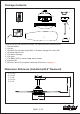
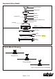
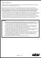
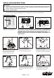
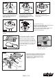
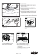

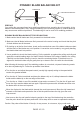

Fig.14
Fig.14a
Antenna
DIP Switch
Transmitter
Receiver
There is a frequency-setter respectively in
the transmitter and receiver. This "DIP
Switch" is a 4 key unit (Fig. 14). All keys
were set at "ON" position in the beginning.
Set the keys to a different code. Make sure
the same numbered keys are switched "ON"
for both DIP Switches (Fig. 14a). Take note
that the "ON" position may have different
orientation in each.
Code example:
1-ON 2-OFF 3-ON 4-OFF
on both DIP Switches.
Fig.15
Move Ground Wires (a), Outlet Box wires (b), and
Motor Wires (c) away from the center of the Hanger
Bracket. Then slide Receiver through Hanger
Bracket as shown, Antenna end first, until it is
centered. Finally, cut Motor Wires (c) to length
needed for connections.
Antenna
Receiver
Hanger
Bracket
a.
b.
c.
Fig.11
(For downrod mount only):
Tighten the ground wire screw.
Slide the pin in. Slide the hanger ball
up into position.
Fig.12
(For downrod mount only):
Tighten the hanger ball screw to the
downrod.
(For downrod mount only):
Thread the motor wires and safety
cable through the canopy as shown.
Then thread the wires and safety cable
through the hanger ball.
Fig.10
Hanger
Ball
Canopy
Motor
Wires
(For downrod mount only):
Thread the motor wires and safety cable
through the downrod stand cover as
shown. Then slide cover down so it
rests on the housing.
Fig.9
Downrod
Stand
Cover
Motor
Wires
(For downrod mount only):
Hang fan on hanger bracket, and rotate the downrod
until the chip on the hanger bracket
snaps into the slot on the hanger ball.
Note: For slope ceiling installation, make sure the
slot of hanger ball and the chip of hanger
bracket are toward the floor.
Slot
Chip
Hanger Bracket
Fig.13
PAGE: 6 / 10
F A N C O
150504
Safety
Cable