
Installation Guide
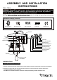

Mounting Screw (B)Mounting plate (A) Rubber Pad (E)
Bolt Nut (D)Wire Connector (C)
191123
Turn on the power at fuse or circuit box
The following parts are available for re-order if damaged or missing.
Spare Parts List:
Mounting Hardware
6192MM (1SET)
Glass Panel
10136CS for T0512
10142CS for T0513
3. Line up the holes in the frame to the set screws of the fixture, secure the frame onto the fixture using bolt nuts-a.
4. Pull out the source wires from the outlet box. Make wire connections using wire connectors (C) as follows:
• Connect the hot wire (usually black insulation) from the fixture to the black wire from the power source.
• Connect the neutral wire (usually white insulation) from the fixture to the white wire from the power source.
• Attach the fixture grounding wire (usually green insulation or bare wire) to the mounting plate unit (A) with the green
grounding screw, then connect it to the house grounding wire with the wire connector (C).
Carefully put all of the wires back into the outlet box.
5. Attach the backplate of the fixture to the mounting plate unit (A) by aligning and inserting the two headless screws from
the mounting plate unit (A) into the open holes on the backplate, then place the two rubber pads (E) over the exposed
headless screws before screwing the two bolt nuts (D).
Note: With silicone caulking compound, caulk completely around where the backplate meets with the wall
surface to prevent water from seeping into the outlet box.
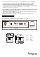
6. Install bulb (not included). See relamping label at socket area or packaging for maximum wattage allowed .
T0512
A: 8"
B: 6-3/4"
C: 9"
T0513
A: 9-1/4"
B: 10"
C: 11-1/2"
B
C
A