
Installation Sheet


151102
ASSEMBLY AND INSTALLATION
INSTRUCTIONS
NOTES: 1. Before installing, consult local electrical codes for wiring and grounding requirements.
2. READ AND SAVE THIS INSTRUCTION.
P0172 / P0174 / P0176 / P0178
WARNING:
TO AVOID RISK OF ELECTRICAL SHOCK, BE SURE TO SHUT OFF
POWER WHILE INSTALLING OR SERVICING THIS FIXTURE.
Hardware Package (included):
Turn off the power at fuse or circuit box.
Installation Steps
Mounting Screw (B)
Wire Nut (F)
Strain Relief(G)
Fixture
Glass Shade
Socket
Mounting Strap (A)
Screw (E)
Green Grounding
Screw (C)
Canopy
Ball Nut(H)
Cord(A)
Fixture Wire
Hex Nut
Socket Ring
Lock Nut (D)
Ball Nut (H)
Bulb Type A Max.60W
(not included)
Strain Relief (G)
Mounting Strap (A)
Lock Nut (D)
Mounting Screw (B)
Green Grounding Screw (C)
Wire Nut (F)
Screw(E)
Outlet Box
A
C(3")
D(3/8")
B(9")
FIG.1
Plastic
Headless
Screw
1. Unscrew two ball nuts, remove mounting strap from canopy.
2. Loosen the plastic headless screw on the canopy using a
flathead screwdriver (not included), .
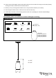
3. Thread the cord through the canopy and Strain Relief. Measure the
desired length of the cord (A) from the canopy to the glass shade and
Leave additional 9" cord (B) above the canopy(include the canopy),
and then cut off the unnecessary cord.(See Fig.1)
4. Adjust strain relief at 9" position from the top of the cord.
5. Mark the 3" cord (C) from the top of the cord (B). Use a knife to peel
off the insulation of the cord (C) carefully to show the 3 inside wires
out. (See Fig. 1)
Caution : Cutting too deep may cut off three inside wires and
destroy the insulation surface of the three inside wires.
6. Peel off the 3 wires from the top about 3/8" long(D) to expose the
copper for wiring.
7. Attach the mounting strap to outlet box by using two mounting screws.
8. Carefully inspect the fixture wires, the NEUTRAL wire (with a white line
along its length), the HOT wire (clear), the GROUND wire (with a green
line along its length) before making wire connections.
9. Pull out the source wires from the outlet box. Make wire connections
using wire nuts as follows:
a. The hot wire marked "L" from the fixture to the black wire from the power source.
b. The neutral wire marked "N" from the fixture to the white wire from the power source.
c. The green grounding wire marked " " from the fixture to the green grounding wire from power source.
Carefully put wires back into the outlet box.