
Installation Guide

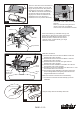


Move Ground Wires (a), Outlet Box wires (b), and
Motor Wires (c) away from the center of the Hanger
Bracket. Then slide Receiver through Hanger
Bracket as shown, Antenna end first, until it is
centered. Finally, cut Motor Wires (c) to length
needed for connections.
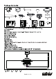
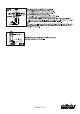
There is a code switch in the transmitter and
receiver. This "DIP Switch" is a 4 key units
(Fig.8). All keys were set at "ON" position in
the beginning. Set the keys to a different
code. Make sure the same numbered keys
are switched "ON" for both DIP switches
(Fig.8a). If the remote controlled fans are
installed than one or the frequency is
interfered, the fan may function abnormally.
Code example:
1-ON 2-OFF 3-ON 4-OFF on both DIP
Switches.
Note: If you have two ceiling fans with 2
remote control units, set 2 different
codes for each set of transmitter / Receiver.
Fig. 8
Antenna
DIP Switch
Transmitter
Receiver
Fig.8a
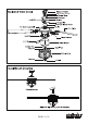
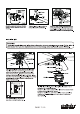
Fig.11
Safety Cable Hook
Safety
Cable
Hang the safety cable into the safety cable hook.
Fig.10
Hanger
Bracket
Hanger
Ball
Receiver
1.
4.
5.
6.
2.3.
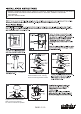
Antenna:
DO NOT CUT
OR SPLICE
Make wire connections:
1) The Motor white wire to the white "To Motor N" wire from
Receiver with a wire connector.
2) The Motor black wire to the black "To Motor L" wire from
Receiver with a wire connector.
3) The Motor blue wire to the blue "For Light" wire from
Receiver with a wire connector.
4) The white wire from Outlet Box to the white "AC in N" wire
from Receiver with a wire connector.
5) The black (hot) wire from Outlet Box to the black "AC in L" wire
from Receiver with a wire connector.
6) The ground wire from Outlet Box to the green ground wire
from the Hanger Ball and the green ground wire from the
Hanger Bracket with a wire connector.
Make sure all of wire connectors are connected firmly.
*** Tuck all wire connectors and wires carefully up into the
Outlet Box.
Fig. 9
Antenna
Receiver
Hanger Bracket
a.
b.
c.
F A N C O
PAGE: 6 / 10
191112