
Installation Guide

ASSEMBLY AND INSTALLATION
INSTRUCTIONS
TO AVOID RISK OF ELECTRICAL SHOCK, BE SURE TO SHUT OFF
POWER BEFORE INSTALLING OR SERVICING THIS FIXTURE.
NOTE: 1. Before installing, consult local electrical codes for wiring and grounding requirements.
2. READ AND SAVE THESE INSTRUCTIONS.
C0235
WARNING:
TO AVOID RISK OF ELECTRICAL SHOCK, BE SURE TO SHUT OFF
POWER WHILE INSTALLING OR SERVICING THIS FIXTURE.
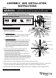
Hardware Package (included):
Turn off the power at fuse or circuit box
Turn on the power at fuse or circuit box
Installation Steps
Mounting Screw (C)Drywall Screw (B) Anchor (A)
Wire Connector (D)
1. Unscrew the four set screws.
Remove the mounting plate unit from the fixture.
2.
2a. For Mounting to wood:
Attach the mounting
plate
unit to the outlet box by using two
mounting screws (C), then secure the drywall screw (B)
through the set hole to the wall.
2b. For Mounting to Drywall:
Place the mounting plate unit to the outlet box and mark the
target on the wall from the set hole for drilling two holes,
remove the mounting plate unit, drill the holes and thread
the anchors (A) into the holes, then attach the mounting
plate unit to the outlet box by using two mounting screws
(C). Secure the drywall screws (B) through the set holes
into the anchors (A).
3. Pull out the source wires from the outlet box. Make wire
connections using wire connectors (D) as follows:
• Connect the hot wire (black insulation) from the fixture to
the black wire from the power source.
• Connect the neutral wire (white insulation) from the fixture to
the white wire from the power source.
• Attach the fixture ground wire (bare wire) to the mounting plate
unit with the green ground screw. Then, depending on local code,
connect it to the house ground wire with the wire connector (D).
Carefully put all of the wires back into the outlet box.
4. Attach the fixture to the mounting plate unit and then secure it with four set screws.
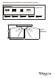
5. Install rods as shown, 225mm metal rods and 232mm glass rods installed alternately at bottom tier, 173mm metal
rods and 178mm glass rods installed alternately at upper tier, 168mm glass rod installed at the center.
6. Install the bulbs (not included). See relamping label at socket area or packaging for maximum wattage allowed.
200907
House Ground Wire
Fixture Ground Wire
Fixture Mounting Screw
Set Screw
Threaded Pipe
Wire Connector (D)
Fixture
Mounting Plate Unit
Anchor (A)
Green Ground Screw
Mounting Screw (C)
Outlet Box
Drywall Screw (B)
Rod
Bulb Type B
Max. 60W
(not included)
232mm Glass Rod
225mm Metal Rod
173mm Metal Rod
168mm Glass Rod
178mm Glass Rod