
Installation Sheet
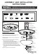
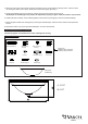

Fig.1
Screw
Key Hole Slot
ASSEMBLY AND INSTALLATION
INSTRUCTIONS
NOTES: 1. Before installing, consult local electrical codes for wiring and grounding requirements.
2. READ AND SAVE THESE INSTRUCTIONS.
C0100 / C0101
Hardware Package (included):
WARNING:
TO AVOID RISK OF ELECTRICAL SHOCK, BE SURE TO SHUT OFF
POWER BEFORE INSTALLING OR SERVICING THIS FIXTURE.
150624
Turn off the power at fuse or circuit box.
Installation Steps
1. Attach the two long screws to the holes on the mounting
strap, thread them in part way: 2 to 3 turns only.
2. Attach the mounting strap to the outlet box using two short
mounting screws.
3. Pull out the source wires from the outlet box. Make wire
connections using wire nuts as follows:
---Connect the hot wire (usually black insulation) from the
fixture to the black wire from the power source.
---Connect the neutral wire (usually white insulation) from
the fixture to the white wire from the power source.
---Attach the fixture grounding wire (usually green insulation
or bare wire) to the mounting strap with the green grounding
screw, and then connect it to the house grounding wire with
the wire nut.
Carefully put the wires back into the outlet box.
Outlet Box
House Grounding Wire
Wire Nut(E)
Long Screw(D)
Ceiling Pan
Socket
Coupling
Lock Nut(H)
Threaded Pipe(J)
Glass Shade
Metal Pad(K)
Lock Nut(H)
Decorative Cup(G)
Finial(F)
Mounting Strap(A)
Green Grounding Screw(C)
Short Mounting Screw(B)
Bulb Type A Max.60W
(not included)
Washer (I)
Lock Nut (H)
Washer (I)
Threaded pipe (J)
Short Mounting
Screw (B)
Green Grounding
Screw (C)
Wire Nut (E)
Mounting Strap (A)
Long
Screw (D)
Metal Pad (K)
Decorative Cup (G)
Finial (F)