
Owner`s manual


4.1 KA65A Internal Processor Registers
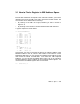
Table 4–2: KA65A Internal Processor Registers
Address
decimal (hex) Register Mnemonic Type
1
Class
2
0 (0) Kernel Stack Pointer KSP R/W 1
1 (1) Executive Stack Pointer ESP R/W 1
2 (2) Supervisor Stack Pointer SSP R/W 1
3 (3) User Stack Pointer USP R/W 1
4 (4) Interrupt Stack Pointer ISP R/W 1
5–7 (5–7) Reserved 3
8 (8) P0 Base P0BR R/W 1
9 (9) P0 Length P0LR R/W 1
10 (A) P1 Base P1BR R/W 1
11 (B) P1 Length P1LR R/W 1
12 (C) System Base SBR R/W 1
13 (D) System Length SLR R/W 1
14–15 (E–F) Reserved 3
16 (10) Process Control Block Base PCBB R/W 1
17 (11) System Control Block Base SCBB R/W 1
1
See Table 4–1.
2
Key to Classes:
1 = Implemented by the KA65A CPU module as specified in the VAX Architecture Refer-
ence Manual.
2 = Implemented uniquely by the KA65A CPU module.
3 = Not implemented. Read as zero; NOP on write. These registers should not be refer-
enced during normal operation as no other instructions can be executed by the CPU un-
til a timeout period that might be longer than device or CPU timeouts has ex-
pired.
4 = Access not allowed; accesses result in a reserved operand fault.
5 = Accessible, but not fully implemented; accesses yield UNPREDICTABLE re-
sults.
6 = Implemented by the FV64 vector module.
n Init = The register is initialized on a KA65A CPU module reset (power-up, system re-
set, and node reset).
KA65A CPU Module Registers 4–3