
Technical data

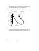

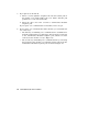


2. Take one end of one of the cords included with the modem (17–00089–
01) and insert it into the top jack on the module cover (modem A). The
top jack is marked with the line icon as shown in Figure 15.
Figure 15: Installing the Telephone Cord (Single-Line and Multiline
Service)
MLO-000654
DFA01 Cover
Panel
Wall-Mounted
Modular
Telephone Jack
Line Icon
Telephone Cord
(17-00089-01)
Modem
A
Modem
B
3. Insert the other end of the cord into the wall-mounted telephone jack.
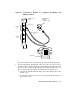
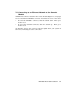
4. To install voice communication on modem A, take the end of the
telephone line that you disconnected from the wall jack in step 1 and
insert it into the second jack from the top of the module cover as shown
in Figure 16. That jack is marked with the telephone icon.
24 VAX 4000 Model 300 Installation