VAX 4000 Model 300 Installation Order Number EK–335AC–IN–003 Digital Equipment Corporation Maynard, Massachusetts
First Printing, March 1990 Revised, February 1991 Revised, June 1991 The information in this document is subject to change without notice and should not be construed as a commitment by Digital Equipment Corporation. Digital Equipment Corporation assumes no responsibility for any errors that may appear in this document. The software, if any, described in this document is furnished under a license and may be used or copied only in accordance with the terms of such license.
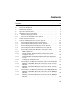
Contents Preface 1 2 3 4 5 5.1 5.2 6 7 7.1 7.2 7.3 7.4 7.5 7.5.1 7.5.2 7.5.3 7.5.4 7.6 7.6.1 7.6.2 7.7 7.7.1 7.7.2 Verify Site Preparation . . . . . . . . . . . . . . . . . . . . . . . . . . . . . Check the Shipment . . . . . . . . . . . . . . . . . . . . . . . . . . . . . . . . Position the System . . . . . . . . . . . . . . . . . . . . . . . . . . . . . . . . Open the System Doors . . . . . . . . . . . . . . . . . . . . . . . . . . . . . Install the Console Terminal . . . . . . . . . . . . . . . . . . .
8 8.1 8.2 8.3 8.4 8.5 9 10 11 12 13 14 15 Connect an Expander, If Required . . . . . . . . . . . Connecting the Q-bus Cables . . . . . . . . . . . . . Connecting the DSSI Cable . . . . . . . . . . . . . . Connecting the KZQSA External Cable . . . . . Connecting the Power Control Bus Cable . . . Connecting the Ground Cable . . . . . . . . . . . . Connect the KZQSA Internal Cable, If Required Connect the DSSI Cable — Dual Host Only . . . . Connect the Ground Cable — Dual Host Only . .
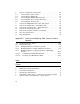
7 8 9 10 11 12 13 14 15 16 17 18 19 20 21 22 23 24 25 26 27 28 29 30 31 32 33 34 System Controls and Indicators — Integrated Storage Element, System Control Panel, and Console Module . . . . . . System Controls and Indicators — TK-Series Tape Drives . . System Controls and Indicators — TF85 Tape Drive . . . . . . . Connecting Devices to a CXA16 or CXB16 Module . . . . . . . . Connecting Devices to the Cable Concentrator . . . . . . . . . . . . Mounting the Cable Concentrator . . . . . . . . . . . . . . . .
35 36 37 38 39 40 41 42 43 44 45 46 47 48 49 Connecting the Power Control Bus Cable . . . . . . . . . . . . . . Connecting the Ground Cable . . . . . . . . . . . . . . . . . . . . . . . TLZ04/KZQSA System Connection . . . . . . . . . . . . . . . . . . . . TLZ04/KZQSA Module Connection — Removing the Terminator . . . . . . . . . . . . . . . . . . . . . . . . . . . . . . . . . . . . . . TLZ04/KZQSA Module Connection — Connecting the Cable Removing the DSSI Terminators . . . . . . . . . . . . . . . . . . . .
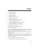
Preface This manual tells you how to install your system, using the following steps. 1. Verify site preparation 2. Check the shipment 3. Position the system 4. Open the system doors 5. Install the console terminal 6. Set the system controls 7. Connect additional devices to the system 8. Connect an expander, if required 9. Connect the KZQSA internal cable, if required 10. Connect the DSSI cable — dual host only 11. Connect the ground cable — dual host only 12. Connect the system power cable 13.
2. After you complete step 7, install the expander as described in the installation document (addendum or manual) shipped with the expander. 3. Return to this manual (step 8) to complete the installation of the expander and the system. NOTE: Some of the devices mentioned in this manual are designed for multiuser systems and may not be suitable for server systems. If you have a server system, contact your Digital representative if you have any questions about whether a device is appropriate for your system.
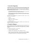
The equipment is not designed for connection to an IT power system (a power system without a directly grounded neutral conductor). The equipment should be plugged into a dedicated (isolated) ground circuit. The system contains an automatic voltage-selection power supply. Voltage selection is not required prior to installation.
1 Verify Site Preparation You may have received a copy of the system Site Preparation manual, which describes the physical, environmental, and electrical requirements for your system. A copy of that manual is also included in your Customer Hardware Information Kit. If you have not done so, read that manual and follow its instructions for preparing your site. • The installation instructions that follow assume your site meets all the requirements listed in the Site Preparation manual.
Depending on your order, your shipment may also include cartons containing: • Additional terminal(s) • Printer(s) • Modem(s) • Expander(s) Make sure your shipment is complete by checking that each item listed as shipped on the Product Delivery Document appears on a Content Listing or on a barcode label on the outside of one of the cartons in your shipment. NOTE: Save all packing materials until you are sure you will not reship any items in the shipment.
Figure 1: Shipping Carton Contents Anti Static Anti Static Keys to Front Door Installation Checklist KZQSA Internal Cable (BC06P-2F) Power Cable Console Terminal Cable (17-01364-02) Ground Wire Cable (12-13756-A8) DSSI Bus Node ID Plugs (12-28766-19) TLZ04 Bus Node ID Plugs (12-28766-28) System Note: Unpacking is illustrated on the exterior of the shipping carton.
3 Position the System You can move your system into position in one of two ways as shown in Figure 2. • Roll it sideways. • Slide or walk it backward or forward by gripping the hand holds on the side of the unit. WARNING: Do not use the hand holds to lift the system. Figure 2: Sliding the System into Position Hand Holds Slides Front to Back Rolls Left to Right MLO-004012 Leave space behind the system for routing cables. Once installation is complete, you can place the system directly against a wall.
4 Open the System Doors The system doors are locked. To unlock and open them: 1. Find the key in the shipping carton (Figure 1). Two keys are provided, one to keep as a spare. 2. Insert the key in the three-position rotary lock shown in Figure 3. Turn the key to the bottom position to open the upper and lower doors as a single unit. 3. Open the doors by pulling the handle on the upper door. Figure 3 shows the door handle.
4. Swing the doors open. Figure 4 shows the system with the upper and lower doors open. Figure 4: Opening the System Doors MLO-004013 Now you are ready to install the console terminal. 5 Install the Console Terminal You will use the console terminal to communicate with your system. 1. Unpack the terminal and its documentation. 2. Use the instructions in the terminal installation guide to connect the various parts of the terminal. 3. Turn on the terminal. The terminal performs a self-test.
Once the terminal passes its self-test, you are ready to perform setup operations. 5.1 Perform Setup Operations Setup instructions for terminals vary according to model or according to which read-only memory (ROM) is installed in the terminal. Be sure to: • Read the documentation provided with your terminal. • Follow the setup instructions for your terminal. NOTE: A new terminal from Digital has the baud rate set to 9600.
4. Feed the other end of the cable under the system from the back or side. Then draw up the cable and insert it into the DEC–423 modular jack shown in Figure 5.
5. Connect the ground lead as shown in Figure 5. a. Loosen the ground screw, above the modular jack. b. Slide the end of the lead under the screw. c. Tighten the screw. You are now ready to set the controls on your system. 6 Set the System Controls The system controls are on the power supply, Integrated Storage Elements, system control panel, console module, and tape drives. 1. Check the setting of the Power switch on the power supply shown in Figure 6. It should be off (set at 0).
2. Check the settings on each RF-series Integrated Storage Element (ISE). One is shown in Figure 7. • Write-Protect button — Make sure that button is in the out (writeenabled) position. • Run/Ready button — Make sure that button is in the in (ready) position. Verify that a bus node ID plug is inserted into each ISE. 3. Check the setting of the Halt button on the system control panel shown in Figure 7. It should be in the out (run) position. 4. Check the settings on the console module shown in Figure 7.
Figure 7: System Controls and Indicators — Integrated Storage Element, System Control Panel, and Console Module ISE Controls and Indicators Run/Ready Button Write-Protect Button Bus Node ID Plug Fault Indicator Console Module Power-Up Mode Switch Baud Rate Select Switch Break Enable/ Disable Switch Baud 300___________0 600___________1 1200__________2 2400__________3 4800__________4 9600__________5 19200_________6 38400_________7 5 System Control Panel Halt Button Restart Button MLO-006034 VAX 400
5. Check the settings on the tape drive. • If a TK-series tape drive is installed in your system, check the setting of the Cartridge Insert/Release handle shown in Figure 8. Make sure that handle is closed (pushed in). Figure 8: System Controls and Indicators — TK-Series Tape Drives Cartridge Insert/Release Handle MLO-006525 • If a TF85 tape drive (Figure 9) is installed in your system: Make sure the Cartridge Insert/Release handle is closed (pushed in).
ad Un lo 85 To Re Han Op P W Un ait res d e m lo s ov le n t ad his e Lig But Ta to ht pe n To H Ha C O Lo nd los Inse and pe Wa it ad le n le e r th th t Ta Lig is is pe ht Ta TF W rit Pr e ot ec te d pe in Us Us e e Cle Ta anin pe g O pe Ha rat nd e le Figure 9: System Controls and Indicators — TF85 Tape Drive Cartridge Insert/ Release Handle Bus Node ID Plug MLO-006604 • You do not have to set controls on the TLZ04 tape drive for system installation.
2. As you complete connections for each module, move left to the next module. The following numbered sections tell you how to connect each type of device. To help you make the proper connections, each module cover has an identifying label at the top. That label contains the module number and option number. Table 1 lists the identifying labels for all modules you can use on your system. Use the table to identify the modules as you connect additional devices to your system.
Table 1 (Cont.
7.1 Connecting Terminals and Serial Printers You can connect up to 16 terminals and/or serial printers for each CXA16 or CXB16 module installed in your system. If your site was prepared properly, the lines for the additional terminals and printers are clearly labeled and terminate near your system. • You do not connect the terminals and printers directly to the system, but to a cable concentrator (H3104) that has connections for up to eight terminals and printers.
• If you are connecting two BC16D cables, connect the first to the connector labeled 8–15 on the module cover. • If you are connecting one BC16D cable, connect that cable to the connector labeled 0–7. Lock the connector in place by using the bail latches.
3. Insert the other end of the BC16D cable into the cable concentrator shown in Figure 11. Lock the connector in place by using the bail latches. Figure 11: Connecting Devices to the Cable Concentrator H3104 Cable Concentrator (Rear View) BC16D Cable H3104 Cable Concentrator (Front View) Modified Modular Jack Bail Latches To Terminals and Printers To System MLO-002274 4. Insert each printer and terminal cable into one of the modified modular jacks on the cable concentrator as shown in Figure 11. 5.
You can mount the cable concentrator on a wall. Wall mounting keeps cables off the floor. Use two screws as shown in Figure 12. Figure 12: Mounting the Cable Concentrator To Wall MLO-000651 NOTE: Be sure you mount the cable concentrator less than 7.6 meters (25 feet) from the system, to ensure the BC16D cable reaches the system. 7.2 Connecting Parallel Printers to the System You can connect up to two parallel printers for each LPV11 module installed in your system.
7.3 Connecting Synchronous Modems to the System You can connect up to two synchronous modems for each DSV11 module installed in your system. To connect a synchronous modem to a DSV11 module, using a protocolspecific adapter and extension cable: 1. Feed the socket end of the 0.6-meter (24-inch) adapter cable (BC19– B/D/E/F) under the system from the back or side and connect it to the module. Tighten the two screws on the cable connector using a screwdriver. 2.
Figure 13: Connecting a Modem to a CXY08 Module Bail Latches BC19N-12 Cable Assembly Feed Cable Under System and Through Opening MLO-004018 3. Attach a modem to one of the four connectors at the opposite end of the cable. If you want to place the modem farther away from the system, attach a BC22F modem cable between the cable assembly and the modem. Refer to your modem documentation for the location of the connector.
7.5 Connecting an Internal Modem to Telephone Lines NOTE: The DFA01 modem is available for U.S. and Canadian customers. Depending on the country you live in, the Telecommunication Administration (PTT) may not let you connect private integral modems to the public switched telephone network. Call your Digital representative for information on modem availability in your country. 7.5.1 DFA01 Modems The DFA01 module contains two modems, A and B. Each requires its own telephone.
Figure 14: Disconnecting the Telephone Line (Single-Line and Multiline Service) Locking Tab Wall-Mounted Modular Telephone Jack Squeeze Locking Tab and Pull from Jack Telephone MLO-000653 VAX 4000 Model 300 Installation 23
2. Take one end of one of the cords included with the modem (17–00089– 01) and insert it into the top jack on the module cover (modem A). The top jack is marked with the line icon as shown in Figure 15. Figure 15: Installing the Telephone Cord (Single-Line and Multiline Service) DFA01 Cover Panel Wall-Mounted Modular Telephone Jack Line Icon Modem A Modem B Telephone Cord (17-00089-01) MLO-000654 3. Insert the other end of the cord into the wall-mounted telephone jack. 4.
Figure 16: Connecting a Modem to a Telephone (Single-Line and Multiline Service) DFA01 Cover Panel Wall-Mounted Modular Telephone Jack Line Icon Modem A Telephone Icon Modem B Telephone MLO-000655 If you do not plan to use modem B, do not perform the following step. 5. Set up modem B by following the same procedure you used to set up modem A. Notice, however, that the jack positions on the module cover are reversed for modem B.
7.5.3 RJ41S/CA41A and RJ45S/CA45A Data-Jack Telephone Service Use the following procedure to connect the DFA01 modem to RJ41S/CA41A or RJ45S/CA45A data-jack telephone service. • You need a standard eight-wire telephone cord (not supplied with the modem). • If you plan to use modems A and B, you need two telephones, one for each modem. Do not unplug the telephone line from the wall-mounted modular telephone jack. 1.
Figure 17: Connecting a Modem to a Wall-Mounted Jack (Data-Jack Service) — Telephone to Wall-Jack Connection DFA01 Cover Panel Line Icon Modem A Telephone Icon Modem B Telephone WallMounted Modular Telephone Jacks MLO-000656 2. Insert the other end of the telephone cord into a second wall-mounted modular telephone jack. If you require voice communication on modem A, refer to step 4. If you do not plan to use modem B, skip step 3 and proceed with step 4.
3. If you plan to use modem B: a. Insert a second eight-wire telephone line into the bottom jack on the module cover, marked with a line icon. (Notice that the jack positions are reversed for modem B.) b. Insert the other end of the cord into a wall-mounted modular telephone jack. If you require voice communication on modem B, refer to step 4. 4.
Figure 18: Connecting a Modem to a Wall-Mounted Jack (Data-Jack Service) — Telephone to DFA01 Connection DFA01 Cover Panel Modem A Modem B Telephone WallMounted Modular Telephone Jacks MLO-000657 a. Leave connected the eight-wire telephone cord that attaches the module cover to a wall-mounted modular telephone jack. b. Disconnect the telephone line from the wall-mounted modular telephone jack. Leave the telephone line connected to the telephone.
c. Connect the telephone line from the telephone to the module cover. • To install voice communication on modem A, insert the telephone line into the second jack from the top of the module cover, marked with the telephone icon. • To install voice communication on modem B, insert the telephone line into the second jack from the bottom of the module cover, marked with the telephone icon. 7.5.
7.6 Connecting to an Ethernet Network at the Console Module An Ethernet Connector switch on the console module (Figure 19, next page) selects a standard or ThinWire connector. You must select one or the other. • To select the ThinWire connector, slide the switch down. Then go to Section 7.6.1. • To select the standard connector, slide the switch up. Section 7.6.2. Then go to An indicator next to the selected connector lights when your system is turned on, indicating an active connection.
Figure 19: Ethernet Connector Switch on the Console Module Ethernet Connector Switch MLO-006035 7.6.1 Making a ThinWire Network Connection at the Console Module To make a ThinWire network connection at the console module: 1. Find the T-connector and two terminators. They are on the ThinWire connector, below the Ethernet Connector switch.
Figure 20 shows how the T-connector, terminators, and ThinWire cable connectors fit together.
2. Remove the terminator from the bottom of the T-connector shown in Figure 21. Push in and turn it counterclockwise until it unlocks. Figure 21: Making a ThinWire Ethernet Connection at the Console Module Terminator T-Connector ThinWire Feed Cable Under System and Through Opening MLO-006036 3. Make sure the T-connector is inserted into the ThinWire connector. Turn the T-connector clockwise to make sure it is locked. 4. Connect the ThinWire cable to the T-connector as shown in Figure 21.
• If your system is a link in a network and connects to two additional components: a. Connect a ThinWire cable to one end of the T-connector. b. Remove the terminator from the other end and connect a second ThinWire cable to it. Push in and turn the connectors clockwise until they lock in place. 5. Connect the ThinWire cable to one of the following devices.
2. Make sure the sliding lock on the standard Ethernet connector on the console module (Figure 22) is in the up position. Then feed the plug end of the cable under the system from the back or side and insert it into the connector. Slide the lock down to secure the connection. Figure 22: Making a Standard Ethernet Connection at the Console Module Ethernet Connector Switch Standard Ethernet Connector Sliding Lock Feed Cable Under System and Through Opening MLO-004022 3.
• A standard adapter in another system or workstation NOTE: Contact your network manager or Digital service representative if you have questions about network configurations. 7.7 Connecting to an Ethernet Network at the DESQA Module If your DESQA module does not have an Ethernet Connector switch (Figure 23, next page): • If you want to connect to ThinWire Ethernet, go to Section 7.7.1. • If you want to connect to standard Ethernet, call your Digital service representative.
Figure 23: DESQA ThinWire/Standard Ethernet Connector Switch Ethernet Connector Switch MLO-004023 7.7.1 Making a ThinWire Network Connection at the DESQA Module If your DESQA module has an Ethernet Connector switch, make sure that switch is set to the out position. A T-connector and two terminators are on the DESQA module. Figure 24 shows how the T-connector, terminators, and ThinWire cable connectors fit together.
Figure 24: ThinWire Cable, T-Connector, and Terminator Connector Connector T-Connector Terminator MLO-000659 To make a ThinWire network connection at the DESQA module: 1. Remove the T-connector from the module. counterclockwise until it unlocks. Push in and turn it 2. Remove the terminators from the T-connector. Push in and turn them counterclockwise until they unlock.
3. Connect the ThinWire cable to the T-connector as shown in Figure 25. Figure 25: Making a ThinWire Ethernet Connection at the DESQA Module ThinWire Ethernet Connector T-Connector Feed Cable Under System and Through Opening MLO-004024 • If your system requires one connection to the network: a. Connect the ThinWire cable to the upper end of the T-connector. b. Connect a terminator to the other end of the T-connector. Push in and turn the connector or terminator clockwise until it locks in place.
4. Insert the T-connector into the ThinWire connector on the module as shown in Figure 25. Push in and turn the T-connector clockwise until it locks in place. 5. Use the cable clamp shipped with the module to form the upper cable in a loop approximately 10 centimeters (4 inches) in diameter as shown in Figure 26. Figure 26: Forming the Upper Cable in a Loop at the DESQA Module Recommended Diameter Is 10 Centimeters (4 Inches) Cable Clamp MLO-004020 6.
When the ThinWire cable is connected to a DEMPR or DESPR, the ground is provided by the DEMPR or DESPR chassis. If you are using a singlesegment ThinWire local area network (LAN) with no DEMPR or DESPR, you may need to ground the ThinWire connector on the DESQA module. CAUTION: Each ThinWire segment must have only one grounding point. To ground a single-segment ThinWire network on the DESQA module, connect a grounding clamp (90–08927–00) and an unshrouded T-connector (12–25534–01) as shown in Figure 27.
Figure 27: Grounding ThinWire Ethernet at the DESQA Module Hole for Address Label Carrier Terminal Ring Ground Wire (14 AWG) Grounding Clamp Terminator T-Connector ThinWire MLO-000664 VAX 4000 Model 300 Installation 43
7.7.2 Making a Standard Network Connection at the DESQA Module If your DESQA module does not have an Ethernet Connector switch, call your Digital service representative. If your DESQA module has an Ethernet Connector switch and you set it to the in (standard) position: 1. Find the Ethernet transceiver cable. It has a plug at one end and a socket at the other end. 2. Make sure the sliding lock on the standard Ethernet connector on the module is in the up position. 3.
• A DELNI interconnect, which can in turn be connected to a baseband Ethernet cable, and which can connect up to eight systems in a local area network NOTE: Contact your network manager or Digital service representative if you have questions about network configurations. 8 Connect an Expander, If Required If you are not installing an expander with your system, skip to step 9. If you are installing an expander with your system: 1.
Figure 29: System Connections for Expanders Q-bus Out KZQSA In Q-bus Out Power Bus Out Ground Wire Out DSSI In/Out MLO-006037 NOTE: The module containing the two Q-bus Out connectors is installed in your system only if you purchased a Q-bus expander (for example, a B400X expander) with your system.
As applicable (follow the instructions that apply to your system), connect one or more of the following expander cables to your system. • Q-bus cables (Section 8.1) • DSSI cable (Section 8.2) • KZQSA external cable (Section 8.3) • Power control bus cable (Section 8.4) • Ground cable (Section 8.5) Then: 1. Complete the installation of the expander as described in the expander document. 2.
8.1 Connecting the Q-bus Cables Connect the two Q-bus cables (BC04V–09) to the two Q-bus Out connectors on your system. Those connectors should be in the last (leftmost) backplane slot used in your system. The module containing those connectors is labeled M9404–PA. Figure 30: Connecting the Q-bus Cables Slide Down to Lock Connector Locking Device J1 J2 MLO-006020 1. Feed the plug end of one of the cables under the system from the back or side and up through the opening.
8.2 Connecting the DSSI Cable Connect the DSSI cable (BC21M–09) to the DSSI In/Out (Bus 0 or Bus 1) connector on your system. 1. For the R400X expander, remove the DSSI terminator (12–29258–01) from the DSSI In/Out (Bus 1) connector, labeled X, on the console module. Figure 31: Removing the DSSI Terminator MLO-006154 Squeeze the spring clips at the top and bottom of the terminator as you pull it straight out.
2. Connect the DSSI cable (BC21M–09) to the DSSI In/Out (Bus 0 or Bus 1) connector by fitting the cable connector over the two guide pins. Figure 32: Connecting the DSSI Cable MLO-004240 Tighten the cable connector screws by hand, then use a screwdriver to secure the connection. 3. If applicable, install the terminator (removed in step 1) on the expander as shown in the expander installation document. 8.3 Connecting the KZQSA External Cable 1.
Figure 33: Removing the KZQSA Terminator Bail Latch MLO-006038 VAX 4000 Model 300 Installation 51
2. Connect the KZQSA external cable (BC06P–06), shipped with the expander, to that connector. Figure 34: Connecting the KZQSA External Cable Bail Latch MLO-006039 Secure the connection by pressing the connector bail latches into place. 3. If applicable, install the terminator (removed in step 1) on the expander, as shown in the expander installation document, or on an external RRDseries drive, as shown in the owner’s manual for that drive.
8.4 Connecting the Power Control Bus Cable Connect the Power Control Bus cable (17–02638–01) to the Power Bus Out (MO) connector. Figure 35: Connecting the Power Control Bus Cable Power Bus Out Connector Power Control Bus Cable MLO-006153 The Power Bus Out connector is on the power supply. It is the topmost of three connectors stacked well below the Power (1/0) switch. NOTE: The Power Control Bus cable is not used in dual-host systems.
8.5 Connecting the Ground Cable Connect the Ground cable (12–13756–A8) to the Ground Wire Out bolt. Figure 36: Connecting the Ground Cable Feed Cable Under System and Through Opening MLO-004028 The Ground Wire Out bolt is on the power supply. It is to the right of the three Power Bus connectors. 9 Connect the KZQSA Internal Cable, If Required The KZQSA internal cable connects the KZQSA module to your system. If a TLZ04 tape drive is not installed in your system, skip to step 10.
Figure 37: TLZ04/KZQSA System Connection KZQSA In DSSI In/Out MLO-006040 2. Remove the protective cover from the KZQSA In connector. 3. Insert the connector on one end of the cable into the KZQSA In connector. Secure the cable connection by pressing the bail latches on the connector until they snap into place.
4. Open the bail latches and remove the terminator from the upper connector on the KZQSA module (M5976–SA) as shown in Figure 38. Figure 38: TLZ04/KZQSA Module Connection — Removing the Terminator Bail Latch MLO-006038 5. Insert the other cable connector into the connector on the KZQSA module as shown in Figure 39.
Figure 39: TLZ04/KZQSA Module Connection — Connecting the Cable Bail Latch MLO-006039 Secure the cable connection by pressing the bail latches on the connector until they snap into place.
10 Connect the DSSI Cable — Dual Host Only If you are not installing a dual-host system, skip to step 12. If you are installing a dual-host system, follow the instructions for this step and the next (step 11). NOTE: If you are installing an expander with your system, for alternate configurations refer to your Dual Host Systems manual. If you want to renumber the system ISEs, refer to your Operation manual. For ease of discussion, call one of the systems host A, the other host B. 1.
Figure 40: Removing the DSSI Terminators Host A Host B MLO-004026 2. Repeat the previous step for host B. 3. Find the 2.74-meter (9-foot) DSSI cable labeled BC21M–09, shipped with your system.
4. Feed either end of that cable under host A from the back or side. Then insert the cable connector into the Bus 0 (DSSI In/Out) connector by fitting the cable connector over the two guide pins shown in Figure 41. Figure 41: Connecting the DSSI Cable Host A Host B MLO-004027 Tighten the screws by hand, then use a screwdriver to secure the connection. 5. Repeat the previous step for host B using the opposite end of the DSSI cable.
11 Connect the Ground Cable — Dual Host Only To connect the ground cable: 1. Find the ground cable (12–13756–A8) shipped with your system. It has a ground-lead terminal on each end. 2. Feed the ground cable under host A from the back or side and up through the opening in the front as shown in Figure 42. Figure 42: Connecting the Ground Cable Feed Cable Under System and Through Opening MLO-004028 3. Locate the Ground Wire Out bolt on host A. It is under the handle on the power supply as shown in Figure 42.
12 Connect the System Power Cable NOTE: Your system contains an automatic voltage-selection power supply. Voltage selection is not required prior to installation. Connect the power cable to your system as follows. 1. Make sure the system Power switch shown in Figure 43 is set to off (0). Figure 43: System Power Switch Power Switch MLO-004263 2. Make sure all devices connected to your system are turned off. 3. Find the power cable shipped with your system. 4.
Figure 44: Power Cable Plugs 100 - 125 V 200 - 250 V MLO-001861 VAX 4000 Model 300 Installation 63
5. Feed the socket end of the cable under the system from the back or side, and insert the cable into the power supply as shown in Figure 45. Figure 45: Connecting the Power Cable to the System Feed Cable Under System and Through Opening MLO-004029 6. Insert the plug end of the cable into your wall outlet or other power source. You are now ready to turn on your system and select a language.
1. Turn on your console terminal and wait until it performs its self-tests successfully. 2. If a B400X or R400X expander is connected to your system, turn on the expander. The AC indicator on the expander power supply should glow orange. 3. Turn on your system by setting the Power switch to on (1). The AC Present indicator, next to that switch, should glow orange. NOTE: If your system contains a B400X or R400X expander linked by a Power Control Bus cable, turning on the system turns on the expander as well.
Within a few moments the console terminal should display a series of numbers as the system tests itself. The example in Figure 47 shows that display after successful testing. Figure 47: Successful System Self-Tests KA670-A Vn.n, VMB n.n Performing normal system tests. 66..65..64..63..62..61..60..59..58..57..56..55..54..53..52..51.. 50..49..48..47..46..45..44..43..42..41..40..39..38..37..36..35.. 34..33..32..31..30..29..28..27..26..25..24..23..22..21..20..19.. 18..17..16..15..14..13..12..11..10..09..08..07..
Figure 48: Saving the Language MLO-004264 Now you are ready to close the system doors. 14 Close the System Doors If you plan to run diagnostic software immediately following the installation, leave the upper door open. If you plan to start up factory-installed software immediately following the installation, leave both doors open.
Close the doors as shown in Figure 49. Figure 49: Closing the System Doors MLO-004030 1. Push gently at the top right of the upper door and the bottom right of the lower door. 2. Turn the key to the middle position (both doors locked) or to the top position (upper door unlocked). 15 After Installation Digital strongly recommends that you run the diagnostic software for your system before you install system software or start factory-installed software the first time.
The diagnostic software is on a tape cartridge labeled MV DIAG CUST TK50. Your system Troubleshooting and Diagnostics manual tells you how to run the diagnostic software. You should now read your system Operation manual to learn how to use the system. You must know how to operate the system controls and the ISE or tape drive before you install system software or run diagnostic software. If you have factory-installed software on your system, see Appendix A for the startup procedure.
Appendix A Starting and Modifying VMS Factory-Installed Software This appendix tells you how to start and modify VMS factory-installed software (FIS), which is on your system disk if you ordered one or more ISEs. FIS must be modified to accommodate customized passwords and system environment particulars. You make the modifications during a startup procedure that is executed when you start FIS the first time. The requirements for modifying FIS depend on how your system will be used.
3. If your system will be part of a cluster or network, ask your network coordinator or system administrator for your system: DECnet node name DECnet node address Cluster group number Cluster password 4. If you are not familiar with networking and clustering, examine the following manuals. VMS VAXcluster Manual Guide to DECnet–VAX Networking VMS Networking Manual A.2 Startup Procedure If you have a dual-host system, you can start with either host. 1. Enter the console mode. a.
>>> SET BOOT DIB0 Return 5. Boot the FIS. >>> BOOT Return 6. Set the Break Enable/Disable switch to disable (down). The system displays a banner and then prompts you for the date and time. VAX/VMS Version Vn.n Major version id = 1 Minor version id = 0 Please enter date and time (DD-MMM-YYYY HH:MM): 7. Enter the date and time in the format shown.
If you enter Y, the system displays the following prompt. Will this node be a cluster member (Y/N)? 3. Enter N. If DECwindows is on the system disk, you will see the following prompt. Do you want DECwindows as the default windowing system? (Y/N) NOTE: It is easy to set DECwindows as the default windowing system at a later stage. To do that, you must modify the VMS system generation parameter, WINDOW_SYSTEM, generate a new set of bootstrap parameters, and boot the system again.
Then the following status message is displayed. Creating RIGHTS database file, SYS$SYSTEM:RIGHTSLIST.DAT Ignore any messages of this type. %SYSTEM-F-DUPIDENT, duplicate identifier The following status message is displayed when the FIS setup procedure completes. %UAF-I-RDBDONEMSG, rights database modified The system then displays messages that remind you to perform certain tasks after the software is installed: • Register any Product Authorization Keys (PAKs). • Back up the system disk.
%LICENSE-I-NOLICENSE, no license is active for this software product %LOGIN-LOGOPRCON, login allowed from OPA0: Welcome to VAX/VMS $ The system prompt ($) indicates the completion of the startup procedure. If you do not enter the correct password, the system displays the following message. User authorization failure If you forget your password, follow the instructions for breaking into the system given in Guide to Setting Up a VMS System. 8. You should now perform the following operations.
VMS VAXcluster Manual, the Guide to DECnet–VAX Networking, and the VMS Networking Manual for more information. A.2.2 Modifying FIS for a Simple VAXcluster Network If you want to use your system as part of a simple VAXcluster network, where disks are shared between different systems in the same network, you need a node name and node ID which you can obtain from your network coordinator. The following procedure configures FIS for use as a server in a simple VAXcluster network.
Enter this cluster’s group number: Enter a number in the range of 1 to 4095 or 61440 to 65535. You can obtain the number from your network coordinator. Enter the cluster’s password: Enter the password. It can be from 1 to 31 alphanumeric characters long and can include dollar signs and underlines. You can obtain it from your network coordinator. Re-enter the cluster’s password for verification: Reenter the password. Will JUPITR be a disk server (Y/N)? Enter Y.
The system displays prompts asking for account passwords. 6. Enter them as shown below. NOTE: The passwords shown are samples. You should enter your own passwords. Remember to record them. If you forget a password, you cannot log in.
Running AUTOGEN -- Please wait At this point, the system shuts itself down and then reboots from the default boot device. The process takes several minutes, and the system displays a series of information messages. SHUTDOWN -- Perform an Orderly System Shutdown VAX/VMS Version Vn.n Major version id = 1 Minor version id = 0 . . . SYSTEM job terminated at 24-JUL-1991 14:47:28.34 Accounting information: Buffered I/O count: 133 Direct I/O count: 12 Page faults: 325 Charged CPU time: 0 00:00:55.23 7.
To register PAKs: $ @SYS$UPDATE:VMSLICENSE Return If you make a mistake while entering a PAK: 1. Continue the data entry sequence. 2. Reject the data at the end of the sequence when your system asks you to confirm the data. Your system then gives you an opportunity to reenter the data correctly. See the VMS License Management Utility Manual for any additional information you may need. Your system Operation manual provides information on backing up the system disk and deleting unwanted files.
See the VMS VAXcluster Manual, the Guide to DECnet–VAX Networking, and the VMS Networking Manual for information on setting up systems as members of complex networks and setting up remote printer and batch processing queues. A.2.3.1 Configuring for Dual-Host Systems The VMS Installation and Operations manual tells you how to configure a dual-host system for cluster operation.
Index A A026–PA module, 15 A030–PA module, 15 A1008–PA module, 15 A1009–PA module, 15 AAV11 option, 15 Additional devices, connecting, 13 ADQ32 option, 15 ADV11 option, 15 After installation, 68 Asynchronous modems, connecting, 20 Attaching See Connecting or Installing AXV11 option, 15 B BA21X–SF option, 15 Before operating system, 68 Boxes, checking, 1 C CA11A, CA12A, and CA13A telephone service, 22 CA41A and CA45A data-jack telephone service, 22 Cables DSSI, connecting, 49 ground, connecting, 54 KZQSA e
Connecting (Cont.
F Factory-installed software See VMS factory-installed software FIS See VMS factory-installed software G Ground cable, connecting, 54 Ground cable, connecting dual hosts, 61 I IBQ01–SA option, 15 IEQ11 option, 15 Installing console terminal, 6 Integrated Storage Elements, setting controls, 10 Internal modem, connecting, 22 ISEs See Integrated Storage Elements K KA670–AA option, 14 KA670–BA option, 14 KDA50 option, 14 KFQSA option, 14 KLESI option, 14 KRQ50 option, 14 KWV11 option, 15 KZQSA external cable
Modems (Cont.
Options (Cont.
System (Cont.