VAX 4000 Model 105A Troubleshooting and Diagnostics Information Order Number: EK–515AB–TS. B01 June 1994 This manual describes the troubleshooting and diagnostic procedures that you can use to solve basic problems with the VAX 4000 Model 105A system.
June 1994 Digital Equipment Corporation makes no representations that the use of its products in the manner described in this publication will not infringe on existing or future patent rights, nor do the descriptions contained in this publication imply the granting of licenses to make, use, or sell equipment or software in accordance with the description.
Contents Preface . . . . . . . . . . . . . . . . . . . . . . . . . . . . . . . . . . . . . . . . . . . . . . . . . . . . . v 1 Troubleshooting and Diagnosing Problems 1.1 1.1.1 1.2 1.2.1 1.2.2 1.3 Troubleshooting . . . . . . . . . . . . . . . . Using the Troubleshooting Table Diagnostic Tests and Commands . . . Power-Up Tests . . . . . . . . . . . . . Self-Tests . . . . . . . . . . . . . . . . . . Contacting Digital Services . . . . . . . . . . . . . . . . . . . . . . . . . . . . . . . . . . . . .
2.5.3 2.5.4 2.6 Display the Service Menu Option . . . . . . . . . . . . . . . . . . . . . . Select Single Device Tests Option . . . . . . . . . . . . . . . . . . . . . Exiting MDM . . . . . . . . . . . . . . . . . . . . . . . . . . . . . . . . . . . . . . . . 2–14 2–15 2–17 Show Configuration Command . . . . . . . . . . . . . . . . . . . . . . . . Listing Diagnostics . . . . . . . . . . . . . . . . . . . . . . . . . . . . . . . . Typical Configuration . . . . . . . . . . . . . . . . . . . . . . . . . . .
Preface This manual describes the troubleshooting and diagnostic procedures that you can use to solve basic problems with the VAX 4000 Model 105A system. This manual is intended for people who have had some experience using computers. This manual has two chapters and an index. See the VAX 4000 Model 105A Operator Information manual for the list of associated and related documents.
1 Troubleshooting and Diagnosing Problems This chapter describes the troubleshooting procedures and diagnostic commands that you can use to solve basic problems with the VAX 4000 Model 105A system. It contains information on the following subjects: • Troubleshooting • Diagnostic tests and commands • Contacting Digital™ Services It also lists the information that you must give to your Digital Services representative and tells you where to find this information. 1.
• Expansion box Q–bus cables • Expansion box DSSI cable(s) • Expansion box power cords • ThinWire™ Ethernet cable or standard Ethernet cable 6.
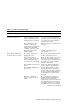
Table 1–1 Basic Troubleshooting Symptom Possible Cause Suggested Solution The power cord is not connected. The power cord may be faulty. The power socket may not be working. Make sure that all the power cords are connected correctly at both ends. Try a power cord that works or test the power socket with an appliance that works. The overload protection circuitry of the power supply may have shut down because of an abnormal condition on the power line. Turn the system off and then turn it back on.
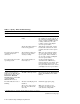
Table 1–1 (Cont.) Basic Troubleshooting Symptom Possible Cause Suggested Solution The terminal cable may be faulty. Connect the terminal cable and the terminal to another system. If the connected terminal works, the console circuitry or MMJ connector is faulty. Otherwise, the cable is faulty. Contact your Digital services representative. The break/enable switch is in the wrong position. Turn off the system unit. Set the break/enable switch to the down position, then turn on the system unit.
Table 1–1 (Cont.) Basic Troubleshooting Symptom Possible Cause Suggested Solution 1 EF/RF-Series Integrated Storage Element (ISE) Problems A read error message displayed; the Run/Ready button is out. Problem in the controller or ISE. If the Fault indicator stops blinking, the system may have corrected itself. Run MDM. If the Fault indicator remains lit, call your Digital service representative. ISE is not spun up. Press the Run/Ready button to the in position.
Table 1–1 (Cont.) Basic Troubleshooting Symptom Possible Cause Suggested Solution RX™26 Diskette Drive Problems The diskette drive is faulty. Contact your Digital Services representative. The diskette density is incorrect. The RX26 accepts only highdensity (HD) or extra-density (ED) diskettes. The diskette drive head may be dirty. See the VAX 4000 Model 105A Operator Information manual for information on how to clean the diskette drive head. The system can read from but cannot write to a diskette.
Table 1–1 (Cont.) Basic Troubleshooting Symptom Possible Cause Suggested Solution TZ30 Tape Drive Problems The tape does not load. Press and release the unload button. Wait for the green LED to turn on before sliding the lever and removing the tape. If the LED flashes, contact your Digital services representative. The system cannot write to the tape. The write-protect switch is in the write-protect position.
Table 1–1 (Cont.) Basic Troubleshooting Symptom Possible Cause Suggested Solution TZK10/TZK11 Quarter-Inch Cartridge (QIC) Tape Drive Problems The data read from the QIC tape is corrupted. The drive head is dirty. Clean the drive head. See the VAX 4000 Model 105A Operator Information manual. The system cannot write to the QIC tape. The write-protect switch is in the write-protect position. Remove the QIC tape, reset the switch and try writing to the QIC tape again.
1.2 Diagnostic Tests and Commands There are a number of diagnostic tests and commands that can help you to isolate a problem with the system unit. These tests and commands are as follows: • Power-up tests • Self-tests1 • Configuration display1 • Error display1 The following sections describe these tests and commands. 1.2.1 Power-Up Tests The system runs the power-up tests each time you turn on the system.
If SIMM_OD is not present or not plugged in correctly, the system responds with a display similar to the following example: KA53-A Vn.n, VMB 2.14 Performing normal system tests. 74..73..72..71..70..69..68..67..66..65..64..63..62.. ? Test_Subtest_DC_88 Loop_Subtest=05 Err_Type=FF DE_NO_Memory_present.
1.2.2 Self-Tests Self-tests perform the same tests as the power-up tests except for one difference; the power-up tests test all the devices in the system, whereas the self-tests allow you to test a single device. Execution of the SHOW CONFIG command produces the display showing the failure of the device DZ, as shown in Example 1–1. Example 1–1 Show Configuration Command >>>SHOW CONF KA53-A Vn.n, VMB 2.
In the example in this section, the show configuration display shows the the DZ device has failed. The self-test number for this device is E4. See Example 1–2. Test E4 should be run by entering T E4 at the console prompt. If the error remains, show the test results to your Digital Services representative. To obtain a listing of the specific tests for the desired device, enter the command shown in the display.
Example 1–2 63 2005CF48 80 200649FC 81 2005CBA8 82 2005CD70 83 20058C70 84 2005A328 85 20057EE4 86 200583A0 90 2005BE54 91 2005BDE8 99 200647D0 9A 2005D1DC 9B 20064680 9C 2005D1A8 9D 2005DEC4 9E 2005C518 9F 20060888 C1 20057B90 C2 20057D68 C5 2005E770 C6 20057AD4 D0 20066C98 D2 20065220 DA 20067FE8 DB 20065A18 DC 200642BC DD 200661FC DE 20065DB4 DF 20065614 E0 20068498 E1 20068578 E2 20068630 E4 200689D4 E8 20068B4C E9 20068BF4 EC 20068CAC (Cont.
Example 1–2 (Cont.
1.3 Contacting Digital Services WARNING Only authorized service personnel should service this equipment. If you have followed the procedures in this chapter but the problem remains unsolved, your Digital services representative can help you. Before you place your call, follow these steps: 1. Write down a description of the problem, including the error messages and the number of the self-tests that failed. 2.
Figure 1–1 Status LED Display 1 3 2 2 1 MLO-010213 Status LED Display Break Enable LED 1–16 Troubleshooting and Diagnosing Problems
Table 1–2 Status LED Display and Break Enable Meanings LED Number Color Meaning LED 0, 1, 2, 3 Green Binary readout indicating certain system tests and functions. LED 4 Green Reset indicator; when extinguished, indicates that the reset is active. LED 5, 6 — Not used LED 7 Amber Clock protection indicator Break Enable LED Green When the break/enable switch is in the up position, the LED is on and you can halt the system by pressing the break key on the console terminal keyboard.
2 Running the Diagnostic Monitor The MicroVAX Diagnostic Monitor (MDM) is an optional software package containing diagnostic tests that isolate and identify faults in your system. MDM also lets you display your system configuration and test how devices work together. MDM is on tape, in a cartridge labeled MV DIAG CUST TK50. MDM operating instructions begin in Section 2.2. CAUTION If your system is connected to a cluster, notify your cluster manager before halting the system to load MDM.
2.1 MDM Limitations MDM tests internal devices in your system, but it performs limited diagnostics. • MDM reads from each drive and checks each controller, but it does not write to the drives because that could destroy data. Note MDM tests a tape or diskette drive only after the medium (tape or diskette) is inserted into the drive. • MDM checks devices on the system as well as the system and interconnects. • MDM checks terminal interfaces (but not terminals) by means of feedback connectors.
2.2.1 Preparing to Run MDM on a Diskless or Tapeless System To run MDM on a diskless or tapeless system that is part of a local area network, you must: • Obtain a MicroVAX Ethernet Server Customer Diagnostics Kit. • Run MDM using the diagnostics in that kit, labeled MV DIAG ENET CUST. Refer to the MicroVAX Diagnostic Monitor Ethernet Server User’s Guide at this time. After you install and downline load MDM, refer again to that manual for instructions on running MDM.
Before running MDM: • Your system must be properly configured. • The Digital Storage Systems Interconnect (DSSI) cable connecting the multiple hosts must be installed. You must run MDM separately for each host. For TKxx based systems, the procedure to use depends on whether one host is a tapeless system (no tape drive) or each host has its own tape drive. Use the procedure in Section 2.2.3.1 to prepare to run MDM in a DSSI VAXcluster with one TKxx tape drive. Use the procedure in Section 2.2.3.
[SYS0.SYSEXE]MDM.SYS (KFQSA adapter or KDA50 controller) Then press Return to continue booting. 7. Run MDM as described in Section 2.3. 8. After you complete the tests on the first host: a. Make sure the Break Enable/Disable switch is set to enable (up) and press the Restart button on that host. b. After the countdown completes and the >>> prompt displays, boot MDM from the second system using the procedure described in steps 2 through 6. c. Run MDM as you did for the first system. 2.2.3.
b. After the self-test countdown completes and the >>> prompt displays, insert the tape cartridge into the tape drive in the second system and lock it in place. c. Enter the command BOOT MUcu, where c is the controller designator and u is the drive unit number, to boot the tape. d. Run MDM as you did for the first system. 2.3 Starting MDM You must start MDM differently for different media: If you are booting MDM from a tape drive, read Section 2.3.1.
2.3.1.1 Booting MDM Manually Use this procedure to boot MDM from a TF-series, TK50 or TK70 tape drive. 1. If software is installed on your system: a. Warn all users to log off. b. Perform system shutdown as described in your software manuals. 2. Make sure the write protect switch on the tape cartridge is in the writeprotect position. 3. If your system contains software, write-protect all disk drives and RF-series ISEs. 4. Move the Break Enable/Disable switch to enable (up). 5. Restart the system. 6.
4. Remove any removable disks, and place all fixed-disk drives and RF-series ISEs off line. 5. Write-protect all disk drives and RF-series ISEs. 6. Turn off your system. 7. Set the Break Enable/Disable switch to disable (down). 8. Turn on your system. 9. After the green light on the tape drive glows steadily, insert the tape cartridge containing MDM into the drive and lock it in place. Loading MDM takes several minutes.
7. Tell your system to load MDM from the disc: For an internal adapter, enter the command BOOT DKxnnn, where x is the adapter designator and nnn is the drive unit number. For a KRQ50 controller, enter the command BOOT/100 DUcu, where c is the controller designator and u is the drive unit number. Then, when your system displays Bootfile:, enter [SYS0.SYSEXE]MDMCD.SYS (the boot file name). Loading MDM takes several minutes. Section 2.4 describes the display you see after loading completes. 8.
2.5 Main Menu Options The Main Menu provides six options as shown below. MAIN MENU Release nnn Version xx.xx 1 - Test the System 2 - Display System Configuration and Devices 3 - Display the System Utilities Menu 4 - Display the Service Menu 5 - Display the Connect/Ignore Menu 6 - Select Single Device Tests Type the number; then press the RETURN key. Note The MDM release and version numbers are represented by nnn and xx.xx respectively in the displays provided throughout this chapter.
Note Because of the similarity of some communication options, MDM sees them as the same device. A CXA16 and CXB16 appear the same to MDM. A generic device name, DH–CX0, is listed for such options, and the last letter in each name shows the difference. For example, DH–CX0A indicates one option, DH–CX0B a second, and so forth.
2.5.2 Display System Configuration and Devices Option The Display System Configuration and Devices option identifies devices recognized by MDM. After you select this option, the diagnostics are prepared for testing. If this is the first option you selected, the diagnostics are loaded and configured. Loading and configuring takes several minutes. After configuring is complete, you are prompted to press Return . After you press Return , the configuration is displayed. See Example 2–1.
Besides the general information listed for each device, more information for specific devices may be given.
• A device other than one from Digital Equipment Corporation is attached to your system. After all devices are listed, you can return to the Main Menu by pressing Return . From the Main Menu you can exit MDM as described in Section 2.6 or you can select one of the other options. 2.5.2.1 Update Drive Unit Number for RRD-Series Function The Update Drive Unit Number function lets you update the unit number for an RRD-series disc drive connected to a KRQ50 controller.
2.5.4 Select Single Device Tests Option The Select Single Device Tests option lets you run tests for a single device. • A functional test is performed on the device circuits. • An exerciser test ensures that the device works properly. After you select this option, the diagnostics are prepared for testing. If this is the first option you selected, the diagnostics are loaded and configured. Loading and configuring takes several minutes. After configuring is complete, you are prompted to press Return .
Note Because of the similarity of some communication options, MDM sees them as the same device. A CXA16 and CXB16 appear the same to MDM. A generic device name, DH–CX0, is listed for such options, and the last letter in each name shows the difference. For example, DH–CX0A indicates one option, DH–CX0B a second, and so forth. Select a device for testing by typing its number and Return . After you press Return , your system configures the device diagnostics and testing begins.
Ethernet controller After a failure message appears, the testing stops. Press Return to return to the Select Single Device Test menu for more testing. To exit MDM, press Section 2.6. Break or the Restart button. For more information, see 2.6 Exiting MDM Exit MDM in one of the following ways: • Press • Press and then release the Halt button. Break . Remove the tape cartridge as described in your Operator Information manual. If you ran MDM on a new system, you are ready to install your software.
Index Booting MicroVAX Diagnostic Monitor See MicroVAX Diagnostic Monitor, starting Console security feature, 1–9 Console terminal checking cable, 1–1 checking power cord, 1–1 turning off, 1–1 turning on, 1–2 C D B Cables checking connections, 1–11 checking the console terminal cable, 1–1 checking the Ethernet cables, 1–2 checking the expansion box power cords, 1–2 checking the expansion box SCSI cables, 1–1 checking the system unit power cord, 1–1 checking the terminal power cord, 1–1 troubleshooting
E K EF/RF-Series controller error, 1–5 duplicate node id, 1–4 fault indicator, 1–4 integrated storage element, 1–4 read error, 1–5 troubleshooting, 1–4 write error, 1–4 Error messages All devices disabled, 2–11 No Dg, 2–13 Unknown, 2–13 Ethernet checking cable, 1–2 Exiting MicroVAX Diagnostic Monitor, 2–17 Expansion boxes checking power cord, 1–2 checking SCSI cables, 1–1 turning off, 1–1 turning on, 1–2 KA53-A, 1–9 KZQSA adapter, booting MicroVAX Diagnostic Monitor, 2–8 F Fan troubleshooting, 1–3 Field
MicroVAX Diagnostic Monitor (cont’d) preparing to run, diskless or tapeless system, 2–3 preparing to run, DSSI VAXcluster, 2–3 preparing to run, DSSI VAXcluster, one TKxx tape drive, 2–4 preparing to run, DSSI VAXcluster, two tape drives, 2–5 preparing to run, hard disk, 2–3 preparing to run, RF-series integrated storage element or hard disk, 2–3 preparing to run, RRD-series disc, 2–2 preparing to run, tapeless system, 2–3 RRD-series disc caddy, preparing, 2–8 running, 2–1 Select Single Device Tests option,
RRD43 compact disc drive troubleshooting, 1–5 Running MicroVAX Diagnostic Monitor, 2–1 RX26 disk format error, 1–5 diskette drive, 1–5 diskette insertion error, 1–5 eject error, 1–6 head cleaning, 1–6 troubleshooting, 1–5 write-protect error, 1–6 S SCSI terminator, 1–2 Security password, 1–9 Select Single Device Tests option, MicroVAX Diagnostic Monitor Main Menu, 2–15 Self-tests, 1–11 running, 1–12 Standard Ethernet, 1–2 Starting MicroVAX Diagnostic Monitor See MicroVAX Diagnostic Monitor, starting Status
TZK10/TZK11 (cont’d) write-protect error, 1–8 U Update Drive Unit Number for RRD40 function, MicroVAX Diagnostic Monitor System Utilities Menu, 2–14 W Write-protect switch RX26, 1–6 TZ30, 1–7 TZK10/TZK11, 1–8 Index–5
How to Order Additional Documentation Technical Support If you need help deciding which documentation best meets your needs, call 800-DIGITAL (800-344-4825) and press 2 for technical assistance. Electronic Orders If you wish to place an order through your account at the Electronic Store, dial 800-234-1998, using a modem set to 2400- or 9600-baud. You must be using a VT terminal or terminal emulator set at 8 bits, no parity.
Reader’s Comments VAX 4000 Model 105A Troubleshooting and Diagnostics Information EK–515AB–TS. B01 Your comments and suggestions help us improve the quality of our publications. Thank you for your assistance.
Do Not Tear – Fold Here and Tape TM BUSINESS REPLY MAIL FIRST CLASS PERMIT NO. 33 MAYNARD MASS.