VAX 4000 Model 105A/106A Troubleshooting and Diagnostics Information Order Number: EK–515AA–TS. B01 MAY 1995 This manual describes the troubleshooting and diagnostic procedures that you can use to solve basic problems with VAX 4000 Model 105A and Model 106A systems.
May 1995 Digital Equipment Corporation makes no representations that the use of its products in the manner described in this publication will not infringe on existing or future patent rights, nor do the descriptions contained in this publication imply the granting of licenses to make, use, or sell equipment or software in accordance with the description.
Contents Preface . . . . . . . . . . . . . . . . . . . . . . . . . . . . . . . . . . . . . . . . . . . . . . . . . . . . . v 1 Troubleshooting and Diagnosing Problems 1.1 1.2 Troubleshooting Procedure . . . . . . . . . . . . . . . . . . . . . . . . . . . . . . Using the Troubleshooting Table . . . . . . . . . . . . . . . . . . . . . . . . . 1–1 1–2 2 Diagnostic Tests and Commands 2.1 2.1.1 2.1.2 2.2 Diagnostic Tests and Commands Power-Up Tests . . . . . . . . . . Self-Tests . . . . . . . . . . . . . .
Tables 1–1 2–1 iv Basic Troubleshooting . . . . . . . . . . . . . . . . . . . . . . . . . . . . . . Status LED Display and Break Enable Meanings . . . . . . . . .
Preface This manual describes the troubleshooting and diagnostic procedures that you can use to solve basic problems with VAX 4000 Model 105A/106A systems. This manual is intended for people who have had some experience using computers. This manual has two chapters and an index. See VAX 4000 Model 105A/106A Operator Information, EK–513AA–OP, for the list of associated and related documents.
1 Troubleshooting and Diagnosing Problems This chapter describes the troubleshooting procedure that you can use to solve basic problems with VAX 4000 Model 105A and Model 106A systems. 1.1 Troubleshooting Procedure If a problem occurs, you must first make sure that all the cables, loopback connectors, and terminators are correctly connected and that the connectors are not damaged, for example, the pins may be broken or short-circuited. Follow these steps: 1.
6. Check that the following terminators, if installed, are correctly connected and are not damaged: • DSSI terminator(s) • SCSI terminator • ThinWire Ethernet terminator (T-connector and two terminators) If you have correctly followed steps 1 to 5, the on/off switches on all the components are set to the off (O) position, and you have solved any problems caused by incorrectly connected cables or terminators. 7.
Table 1–1 Basic Troubleshooting Symptom Possible Cause Suggested Solution The power cord is not connected. The power cord may be faulty. The power socket may not be working. Make sure that all the power cords are connected correctly at both ends. Try a power cord that works or test the power socket with an appliance that works. The overload protection circuitry of the power supply may have shut down because of an abnormal condition on the power line. Turn the system off and then turn it back on.
Table 1–1 (Cont.) Basic Troubleshooting Symptom Possible Cause Suggested Solution The terminal cable may be faulty. Connect the terminal cable and the terminal to another system. If the connected terminal works, the console circuitry or MMJ connector is faulty. Otherwise, the cable is faulty. Contact your Digital services representative. The break/enable switch is in the wrong position. Turn off the system unit. Set the break/enable switch to the down position, then turn on the system unit.
Table 1–1 (Cont.) Basic Troubleshooting Symptom Possible Cause Suggested Solution EF/RF-Series Integrated Storage Element (ISE) Problems A read error message displayed; the Run/Ready button is out. 1 Problem in the controller or ISE. If the Fault indicator stops blinking, the system may have corrected itself. Run MDM. If the Fault indicator remains lit, call your Digital service representative. ISE is not spun up. Press the Run/Ready button to the in position.
Table 1–1 (Cont.) Basic Troubleshooting Symptom Possible Cause Suggested Solution The TZ30 green LED flashes rapidly. The drive mechanism is faulty or the tape cartridge is damaged. Press and release the unload button to clear the fault. If the LED continues to flash, do not try to remove the tape cartridge or use the tape drive. Contact your Digital services representative. The TZ30 does not operate. The drive does not contain a tape cartridge. Insert the tape cartridge and press the unload button.
Table 1–1 (Cont.) Basic Troubleshooting Symptom Possible Cause Suggested Solution TLZ06/TLZ07 Cassette Tape Drive Problems The system cannot write to the cassette tape. The write-protect switch is in the write-protect position. If the write-protect LED is on, remove the tape, reset the switch and try writing to the tape again. If the problem persists, contact your Digital services representative. The cassette tape is not loaded. Load the cassette tape. The write-protect LED flashes.
2 Diagnostic Tests and Commands This chapter describes the diagnostic commands that you can use to solve basic problems with VAX 4000 Model 105A and Model 106A systems. If you need to contact Digital services for further assistance, this chapter also lists the information that you must give to your Digital services representative, and tells you where to find this information. 2.
! " KA53-A Vn.n, VMB 2.14 Performing normal system tests. 74..73..72..71..70..69..68..67..66..65..64..63..62..61..60..59.. 58..57..56..55..54..53..52..51..50..49..48..47..46..45..44..43.. 42..41..40..39..38..37..36..35..34..33..32..31..30..29..28..27.. 26..25..24..23..22..21..20..19..18..17..16..15..14..13..12..11.. 10..09..08..07..06..05..04..03.. Tests completed.
If SIMM_OD is not present or not plugged in correctly, the system responds with a display similar to the following example: KA53-A Vn.n, VMB 2.14 Performing normal system tests. 74..73..72..71..70..69..68..67..66..65..64..63..62.. ! ? Test_Subtest_DC_88 Loop_Subtest=05 Err_Type=FF DE_NO_Memory_present.
2.1.2 Self-Tests Self-tests perform the same tests as the power-up tests except for one difference; the power-up tests test all the devices in the system, whereas the self-tests allow you to test a single device. Execution of the SHOW CONFIG command produces the display showing the failure of the device DZ, as shown in Example 2–1. Example 2–1 Show Configuration Command >>>SHOW CONF KA53-A Vn.n, VMB 2.
In the example in this section, the show configuration display shows the the DZ device has failed. The self-test number for this device is E4. See Example 2–2. Test E4 should be run by entering T E4 at the console prompt. If the error remains, show the test results to your Digital Services representative. To obtain a listing of the specific tests for the desired device, enter the command shown in the display.
Example 2–2 63 2005CF48 80 200649FC 81 2005CBA8 82 2005CD70 83 20058C70 84 2005A328 85 20057EE4 86 200583A0 90 2005BE54 91 2005BDE8 99 200647D0 9A 2005D1DC 9B 20064680 9C 2005D1A8 9D 2005DEC4 9E 2005C518 9F 20060888 C1 20057B90 C2 20057D68 C5 2005E770 C6 20057AD4 D0 20066C98 D2 20065220 DA 20067FE8 DB 20065A18 DC 200642BC DD 200661FC DE 20065DB4 DF 20065614 E0 20068498 E1 20068578 E2 20068630 E4 200689D4 E8 20068B4C E9 20068BF4 EC 20068CAC (Cont.
Example 2–2 (Cont.
2.2 Contacting Digital™ Services WARNING Only authorized service personnel should service this equipment. If you have followed the procedure in this chapter but the problem remains unsolved, your Digital services representative can help you. Before you place your call, follow these steps: 1. Write down a description of the problem, including the error messages and the number of the self-tests that failed. 2.
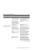
Figure 2–1 Status LED Display 1 3 2 2 1 MLO-011847 ! " Status LED Display Break Enable LED Diagnostic Tests and Commands 2–9
Table 2–1 Status LED Display and Break Enable Meanings LED Number Color Meaning LED 0, 1, 2, 3 Green Binary readout indicating certain system tests and functions. LED 4 Green Reset indicator; when extinguished, indicates that the reset is active. LED 5, 6 — Not used LED 7 Amber Clock protection indicator Break Enable LED Green When the break/enable switch is in the up position, the LED is on and you can halt the system by pressing the break key on the console terminal keyboard.
Index DSSI terminator, 1–2 C Cables checking connections, 2–4 checking the console terminal cable, 1–1 checking the Ethernet cables, 1–1 checking the expansion box power cords, 1–1 checking the expansion box SCSI cables, 1–1 checking the system unit power cord, 1–1 checking the terminal power cord, 1–1 troubleshooting, 1–1 Connections checking SCSI terminator, 1–2 checking standard Ethernet loopback connector, 1–2 checking ThinWire Ethernet terminator, 1–2 Console security feature, 2–1 Console terminal che
L S Loopbacks checking, 1–1 standard Ethernet, 1–1 SCSI terminator, 1–2 Security password, 2–1 Self-tests, 2–4 running, 2–5 Standard Ethernet, 1–2 Status LED display, 2–9 location, 2–9 System unit checking power cord, 1–1 troubleshooting, 1–3 turning off, 1–1 turning on, 1–2 O Operating system software troubleshooting, 1–3 P Peripherals turning off, 1–1 turning on, 1–2 Power cord troubleshooting, 1–3 Power-up display troubleshooting, 1–3 Power-up tests successful display, 2–1 unsuccessful display, 2–3
TZ30 green LED, 1–6 head cleaning, 1–6 operate lever faults, 1–6 tape drive, 1–5 troubleshooting, 1–5 unload button, 1–6 write-protect error, 1–6 TZK10/TZK11 amber LED, 1–7 head cleaning, 1–7 QIC tape drive, 1–7 troubleshooting, 1–7 write-protect error, 1–7 W Write-protect switch TZ30, 1–6 TZK10/TZK11, 1–7 Index–3
Reader’s Comments VAX 4000 Model 105A/106A Troubleshooting and Diagnostics Information EK–515AA–TS. B01 Your comments and suggestions help us improve the quality of our publications. Thank you for your assistance.
d Do Not Tear – Fold Here and Tape TM BUSINESS REPLY MAIL FIRST CLASS PERMIT NO. 33 MAYNARD MASS.