VAX 4000 Model 105A/106A Installation Information Order Number: EK–512AA–IN. B01 May 1995 This manual describes how to install and test the VAX 4000 Model 105A and Model 106A.
May 1995 Digital Equipment Corporation makes no representations that the use of its products in the manner described in this publication will not infringe on existing or future patent rights, nor do the descriptions contained in this publication imply the granting of licenses to make, use, or sell equipment or software in accordance with the description.
Contents Preface . . . . . . . . . . . . . . . . . . . . . . . . . . . . . . . . . . . . . . . . . . . . . . . . . . . . . v 1 Installation Procedure Step Step Step Step Step Step Step Step Step Step Step Step 1: Choosing a Suitable Location . . . . . . . . . . . . . . . . . 2: Unpacking the System and Identifying the Parts . . 3: Connecting the Console Terminal . . . . . . . . . . . . . . 4: Connecting the ThinWire Terminator . . . . . . . . . . . 5: Connecting the SCSI Terminator . . . . . . . . . . .
1–6 1–7 1–8 iv Connecting a DSSI Terminator to a VAX 4000 Model 106A . . . . . . . . . . . . . . . . . . . . . . . . . . . . . . . . . . . . . . . . . . . . Power Cord Connection . . . . . . . . . . . . . . . . . . . . . . . . . . . . . Power Turn On . . . . . . . . . . . . . . . . . . . . . . . . . . . . . . . . . . .
Preface This manual describes how to install and test VAX 4000 Model 105A and Model 106A systems. It also refers to information on connecting the system to a network, connecting external options to the system, and booting the operating system. Audience This manual is intended for anyone who wants to install VAX 4000 Model 105A/106A systems. It is written for both experienced and inexperienced users. Structure of This Manual This manual contains one chapter.
Conventions The following conventions are used in this manual: vi Convention Description MONOSPACE Text displayed on the screen is shown in monospace type. italic type Italic type emphasizes important information and indicates the complete titles of manuals. Note A note contains information that is of special importance to the user.
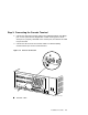
1 Installation Procedure This chapter shows you, step by step, how to install VAX 4000 Model 105A and Model 106A systems. Note Illustrations in this manual show a VAX 4000 Model 106A system rather than a Model 105A system, unless otherwise noted. Step 1: Choosing a Suitable Location Follow these guidelines when choosing where to place the system unit: • Place the system unit where the room temperature is between 10°C and 40°C (50°F and 104°F) and the humidity is between 20% and 80%.
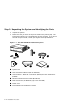
Step 2: Unpacking the System and Identifying the Parts 1. Unpack the system. 2. Make sure that you have all the parts listed on the packing slip. The loose-piece accessory kit is shipped with all basic systems. If you do not have all the parts listed, contact your Digital Sales representative.
Step 3: Connecting the Console Terminal 1. Connect one end of the terminal cable to the modified modular jack (MMJ) port 3. This system will be shipped with a label covering ports 0 and 1. After port 3 is properly identified as the console port, the OPA0 arrow label may be removed. 2. Connect the other end of the terminal cable to a DEC423 (MMJ) communications port on the console terminal.
Step 4: Connecting the ThinWire Terminator 1. Assemble the T-connector and the two terminators to form a ThinWire terminator. 2. Connect the ThinWire terminator to the system unit.
Step 5: Connecting the SCSI Terminator 1. Connect the SCSI terminator to the SCSI port. 2. Close the bail lock loops.
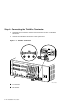
Step 6: Connecting the DSSI Terminators Connect all DSSI terminators. Note The VAX 4000 Model 105A has an expansion port with three DSSI slots (see Figure 1–5). The VAX 4000 Model 106A has four DSSI slots on the expansion port (see Figure 1–6).
Figure 1–6 Connecting a DSSI Terminator to a VAX 4000 Model 106A 1 2 1 3 2 MLO-011871 ! " DSSI Terminator for all models Connected DSSI Terminators Installation Procedure 1–7
Step 7: Connecting the Power Cord 1. Ensure that the on/off switch is in the off (O) position (see Figure 1–8 for switch location). 2. Connect the power cord to the system unit. 3. Connect the other end of the power cord to an isolated, grounded circuit.
Step 8: Turning on the Console Terminal and System Unit 1. Turn on the console terminal. Wait until it completes its power-up test. (See the terminal documentation for more information.) 2. Check the terminal settings. See the VAX 4000 Model 105A/106A Operator Information manual for the list of correct settings. 3. Turn on the system unit by setting the on/off switch to the on ( | ) position.
Step 9: Checking the Power-Up Test Results The power-up test can take several minutes to complete, depending on the number of installed options and on which default settings you use. 1. If the power-up test results displayed on the screen are similar to the results in Example 1–1, the system has passed the power-up test. Go to step 9. 2. If the power-up test results displayed on the screen are not similar to the results in Example 1–1, the system has not passed the power-up test.
If SIMM_OD is not present or not plugged in correctly, the system responds with a display similar to the following example: Example 1–2 Unsuccessful Power-Up Test Screen KA53-A VX.X, VMB 2.14 Performing normal system tests. 72..71..70..69..68..67..66..65..64..63..62.. ! ? Test_Subtest_DC_88 Loop_Subtest=05 Err_Type=FF DE_NO_Memory_present.
Step 10: Connecting the System to a Network If you want to connect the system to a network, see the VAX 4000 Model 105A/106A Operator Information manual. Step 11: Connecting External Options to the System If you want to connect external options to the system, see the VAX 4000 Model 105A/106A Operator Information manual. Step 12: Booting the Operating System The system is supplied with factory installed software (FIS) on the system disk.
Reader’s Comments VAX 4000 Model 105A/106A Installation Information EK–512AA–IN. B01 Your comments and suggestions help us improve the quality of our publications. Thank you for your assistance.
d Do Not Tear – Fold Here and Tape TM BUSINESS REPLY MAIL FIRST CLASS PERMIT NO. 33 MAYNARD MASS.