
Operator`s manual
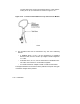


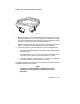


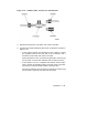


Figure 2–29: Ethernet Transceiver Cable
MLO-007143
2. Make sure the lock on the standard Ethernet connector on the console
bulkhead assembly is in the forward position. Feed the plug under
the cable management bracket from the rear of the cabinet and insert
it into the socket on the console bulkhead assembly.
Slide the locking device back on the socket to secure the connection.
Figure 2–30 shows a standard Ethernet network connection.
3. Connect the other end of the cable to one of the following devices:
• An H4000 or H4005 transceiver located on a traditional baseband
Ethernet cable.
• A DELNI which, in turn, can be connected to a baseband Ether-
net cable, and can connect up to eight systems in a LAN.
• A DESTA adapter, which allows you to connect the Ethernet
transceiver cable to ThinWire Ethernet cabling.
The Digital Network and Communications publications explain the types
of network configurations possible.
NOTE
Contact your network manager or Digital service repre-
sentative if you have questions concerning network con-
figurations.
Installation 2–47